-
LM36011 Inductorless, Single-LED Flash Driver With 1.5-A High-Side Current Source
- 1 Features
- 2 Applications
- 3 Description
- 4 Revision History
- 5 Pin Configuration and Functions
- 6 Specifications
- 7 Detailed Description
- 8 Applications and Implementation
- 9 Power Supply Recommendations
- 10Layout
- 11Device and Documentation Support
- 12Mechanical, Packaging, and Orderable Information
- IMPORTANT NOTICE
Package Options
Refer to the PDF data sheet for device specific package drawings
Mechanical Data (Package|Pins)
- YKB|8
Thermal pad, mechanical data (Package|Pins)
Orderable Information
LM36011 Inductorless, Single-LED Flash Driver With 1.5-A High-Side Current Source
1 Features
- Accurate and Programmable LED Currents
- Flash / IR Currents Ranging from 11 mA up to 1.5 A (128 Levels)
- Torch Currents Ranging from 2.4 mA up to 376 mA (128 Levels)
- Flash Time-Out up to 1.6 Seconds
- Optimized Flash LED Current During Low Battery Conditions (IVFM)
- Grounded Cathode LED Operation for Improved Thermal Management
- Small Total Solution Size: < 4 mm2
- Hardware Strobe Enable (STROBE)
- Input Voltage Range from 2.5 V to 5.5 V
- 400-kHz I2C-Compatible Interface
- I2C Address = 0x64
2 Applications
- Mobile Phones
- Tablets
- IR LED Driver
- Video Surveillance: IP Camera
- Barcode Scanner
- Portable Data Terminal
3 Description
The LM36011 is an ultra-small LED flash driver that provides a high level of adjustability. With a total solution size of 4 mm2, it can produce up to 1.5 A of LED flash current or up to 376 mA of torch current. This is all done from a accurately programmable current source without the need of a pre-regulated voltage, which saves on solution size and cost.
Features of the LM36011 are controlled via an I2C-compatible interface. These features include: hardware flash (STROBE), flash time-out, UVLO, thermal scale-back, LED fault detection, and 128 programmable currents for both flash and movie mode (torch). The device operates over a –40°C to +85°C ambient temperature range.
Device Information(1)
| PART NUMBER | PACKAGE | BODY SIZE (NOM) |
|---|---|---|
| LM36011 | DSBGA (8) | 1.512 mm × 0.800 mm |
- For all available packages, see the orderable addendum at the end of the data sheet.
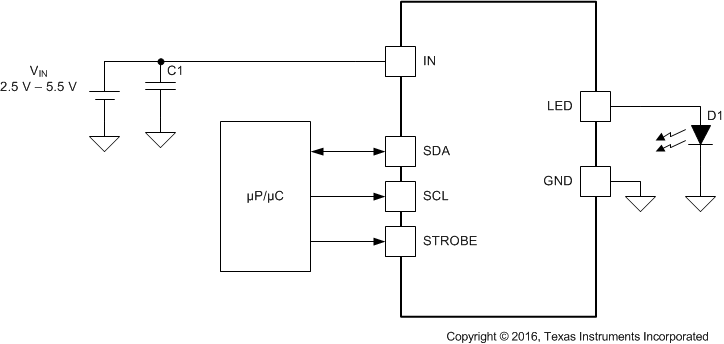
Simplified Schematic
4 Revision History
Changes from * Revision (July 2017) to A Revision
- Corrected package dimensions Go
5 Pin Configuration and Functions
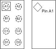
Pin Functions
| PIN | TYPE(1) | DESCRIPTION | |
|---|---|---|---|
| NAME | NO. | ||
| A1 | GND | G | Ground |
| A2,C1 | IN | P | Input voltage connection. Connect IN to the input supply and bypass to GND with a 10-µF or larger ceramic capacitor. |
| B2 | STROBE | I | Active high hardware flash enable. Drive STROBE high to turn on flash pulse. An internal pulldown resistor of 300 kΩ is between STROBE and GND. |
| C2 | SDA | I/O | I2C serial data input/output. |
| D1 | LED | P | High-side current source output for flash LED. |
| D2 | SCL | I | I2C serial clock input. |
| B1 | No Connect | — | No connect |
6 Specifications
6.1 Absolute Maximum Ratings
over operating free-air temperature range (unless otherwise noted)(1)(2)| MIN | MAX | UNIT | ||
|---|---|---|---|---|
| IN, OUT, LED | −0.3 | 6 | V | |
| SDA, SCL, STROBE | −0.3 | (VIN+ 0.3) w/ 6 V maximum | ||
| Continuous power dissipation(3) | Internally limited | |||
| Junction temperature, TJ-MAX | 150 | °C | ||
| Storage temperature, Tstg | −65 | 150 | °C | |
6.2 ESD Ratings
| VALUE | UNIT | |||
|---|---|---|---|---|
| V(ESD) | Electrostatic discharge | Human-body model (HBM), per ANSI/ESDA/JEDEC JS-001(1) | ±1000 | V |
| Charged-device model (CDM), per JEDEC specification JESD22-C101(2) | ±250 | |||
6.3 Recommended Operating Conditions
over operating free-air temperature range (unless otherwise noted)(1)(2)| MIN | MAX | UNIT | ||
|---|---|---|---|---|
| VIN | 2.5 | 5.5 | V | |
| Junction temperature, TJ | −40 | 125 | °C | |
| Ambient temperature, TA (3) | −40 | 85 | °C | |
6.4 Thermal Information
| THERMAL METRIC(1) | LM36011 | UNIT | |
|---|---|---|---|
| YKB (DSBGA) | |||
| 8 PINS | |||
| RθJA | Junction-to-ambient thermal resistance | 117.3 | °C/W |
| RθJC(top) | Junction-to-case (top) thermal resistance | 1.3 | °C/W |
| RθJB | Junction-to-board thermal resistance | 34.3 | °C/W |
| ΨJT | Junction-to-top characterization parameter | 0.5 | °C/W |
| ΨJB | Junction-to-board characterization parameter | 34.6 | °C/W |
6.5 Electrical Characteristics
TA = 25°C and VIN = 3.6 V, unless otherwise specified. Minimum and maximum limits apply over the full operating ambient temperature range (–40°C ≤ TA ≤ 85°C).(1)(2)| PARAMETER | TEST CONDITIONS | MIN | TYP | MAX | UNIT | ||
|---|---|---|---|---|---|---|---|
| CURRENT SOURCE SPECIFICATIONS | |||||||
| ILED | Current source accuracy | VIN = 4 V, flash code = 0x7F = 1.5 A (3) | –10% | 1.5 | 10% | A | |
| VIN = 4 V, torch code = 0x7F = 376 mA | –10% | 376 | 10% | mA | |||
| VHR | LED current source regulation voltage | ILED = 1.5 A | Flash | 550 | mV | ||
| ILED = 376 mA | Torch | 350 | |||||
| STEP-UP DC-DC CONVERTER SPECIFICATIONS | |||||||
| VUVLO | Undervoltage lockout threshold | Falling VIN | 2.5 | V | |||
| VIVFM | Input voltage flash monitor trip threshold | Reg 0x02, bits [7:5] = 000 | –3% | 2.9 | 3% | V | |
| IQ | Quiescent supply current | 0.3 | mA | ||||
| ISB | Standby supply current | Device disabled 2.5 V ≤ VIN ≤ 5.5 V |
0.8 | 4 | µA | ||
| STROBE VOLTAGE SPECIFICATIONS | |||||||
| VIL | Input logic low | 2.5 V ≤ VIN ≤ 5.5 V | 0 | 0.4 | V | ||
| VIH | Input logic high | 1.2 | VIN | V | |||
| I2C-COMPATIBLE INTERFACE SPECIFICATIONS (SCL, SDA) | |||||||
| VIL | Input logic low | 2.5 V ≤ VIN ≤ 4.2 V | 0 | 0.4 | V | ||
| VIH | Input logic high | 1.2 | VIN | ||||
| VOL | Output logic low | ILOAD = 3 mA | 400 | mV | |||
6.6 Timing Requirements
| MIN | NOM | MAX | UNIT | ||
|---|---|---|---|---|---|
| t1 | SCL clock period | 2.4 | µs | ||
| t2 | Data in set-up time to SCL high | 100 | ns | ||
| t3 | Data out stable after SCL low | 0 | ns | ||
| t4 | SDA low set-up time to SCL low (start) | 100 | ns | ||
| t5 | SDA high hold time after SCL high (stop) | 100 | ns | ||
 Figure 1. I2C-Compatible Interface Specifications
6.7 Typical Characteristics
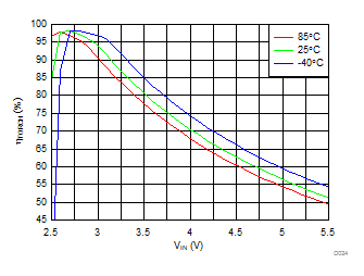
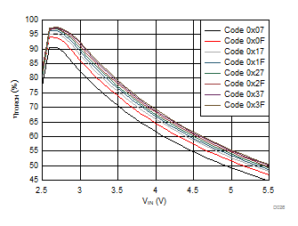
TA = 25°C, VIN = 3.6 V, CIN = 10 µF, VLED = 3.4 V, Flash Time-out = 320 ms and Thermal Scale-Back (TSB) disabled, unless otherwise noted.
| VIN = 4 V |

| IFLASH = 1.03 A |


| ITORCH = 258 mA |


| Mode (Reg 0x01 bits[1:0]) = 01 (IR Mode) | ||


| IFLASH = 1.5 A |

| IFLASH = 0.75 A |


| ITORCH = 376 mA |

| ITORCH = 188 mA |


| Mode (Reg 0x01 bits[1:0]) = 10 (Torch Mode) | ||
7 Detailed Description
7.1 Overview
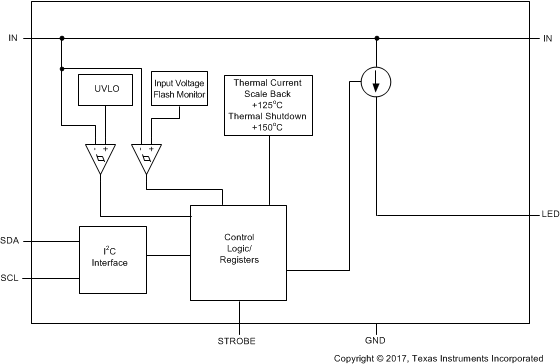
The LM36011 is a high-power white LED flash driver capable of delivering up to 1.5 A to the LED over the 2.5-V to 5.5-V input voltage range.
The device has one logic input for a hardware flash enable (STROBE). This logic input has an internal 300-kΩ (typical) pulldown resistor to GND.
Additional features of the device include an input voltage monitor that can reduce the flash current during low VIN conditions and a temperature based current scale-back feature that forces the flash current to the set torch level if the on-chip junction temperature reaches 125°C.
Control is done via an I2C-compatible interface. This includes adjustment of the flash and torch current levels, and changing the flash time-out duration. Additionally, there are flag and status bits that indicate flash current time-out, LED over-temperature condition, LED failure (open/short), device thermal shutdown, thermal current scale-back, and VIN undervoltage conditions.
7.2 Functional Block Diagram
7.3 Feature Description
7.3.1 Flash Mode
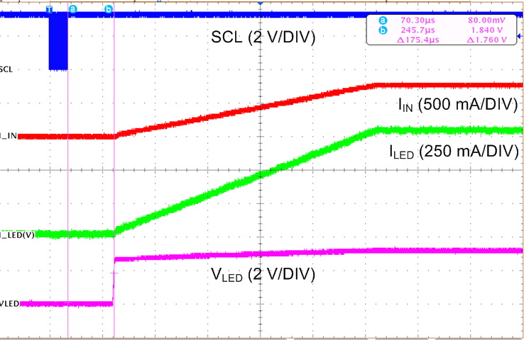
In flash mode, the LED current source provides 128 target current levels from 11 mA to 1.5 A, set by the LED Flash Brightness Register (0x03 bits [6:0]). Flash mode is activated by the Enable Register (0x01), setting mode M1, M0 (bits [1:0]) to 11. Once the flash sequence is activated, the LED current source ramps up to the programmed flash current by stepping through all current steps until the programmed current is reached.
When flash mode is enabled using the mode M1, M0 (bits [1:0]) of the Enable Register (0x01), the mode bits in the Enable Register are cleared after a flash time-out event.
7.3.2 Torch Mode
In torch mode, the LED current source provides 128 target current levels from 2.4 mA to 376 mA, set by the LED Torch Brightness Register (0x04 bits [6:0]). Torch mode is activated by the Enable Register (0x01), setting mode M1, M0 (bits [1:0]) to 10. Once the TORCH sequence is activated, the LED current source ramps up to the programmed torch current by stepping through all current steps until the programmed current is reached. The rate at which the current ramps is determined by the value chosen in the Torch Ramp bit [0] in Timing Register (0x02).
7.3.3 IR Mode
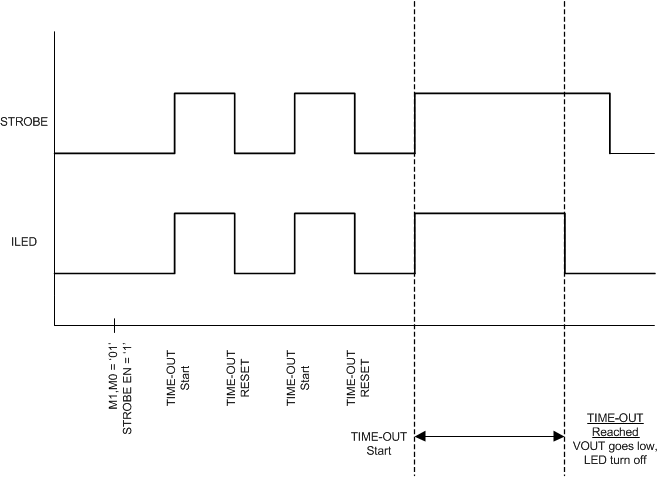
In IR mode, the target LED current is equal to the value stored in the LED Flash Brightness Register (0x03 bits [7:0]). IR mode is enabled by the Enable Register (0x01) setting mode M1, M0 (bits [1:0]) to 01. In IR mode, toggling the STROBE pin enables and disables the LED current source. The STROBE pin can only be set to be Level sensitive, as all timing of the IR pulse is externally controlled. In IR mode, the current source does not control the ramp rate of the LED output. The current transitions immediately from off to on and then on to off.
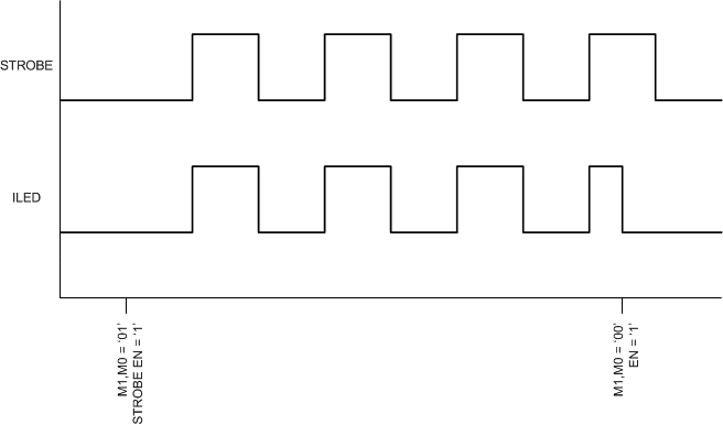 Figure 17. IR Mode
7.4 Device Functioning Modes
7.4.1 Start-Up (Enabling The Device)
At turnon the LED current source steps through each FLASH or TORCH level until the target LED current is reached. This gives the device a controlled turnon and limits inrush current from the VIN supply. The target LED flash and the target LED torch currents are set by the LED Flash Brightness Register (0x03 bits [6:0]) and LED Torch Brightness Register (0x04 bits [6:0]) respectively.
7.4.2 Input Voltage Flash Monitor (IVFM)
The LM36011 has the ability to adjust the flash current based upon the voltage level present at the IN pin utilizing the input voltage flash monitor (IVFM). The adjustable threshold IVFM-D ranges from 2.9 V to 3.6 V in 100-mV steps and is set by Configuration Register (0x02) bits [7:5]. Additionally, the IVFM-D threshold sets the input voltage boundary that forces the LM36011 to stop ramping the flash current during start-up.
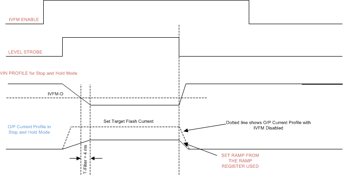 Figure 19. IVFM Mode
7.4.3 Fault/Protections
Upon a fault condition, the LM36011 sets the appropriate flag(s) in the Flags Register (0x05) and switches into stand-by mode obtained by clearing the mode M1, M0 (bits [1:0]) of the Enable Register (0x01). The LM36011 remains in standby until an I2C read of the Flags Register. I2C read of the Flags Register clears the flags and the fault status can be re-checked. If the fault(s) is still present, the LM36011 re-sets the appropriate flag bits and enters stand-by again.
7.4.3.1 Input Voltage Flash Monitor (IVFM)
When the input voltage crosses the IVFM-D value, programmed by Configuration Register (0x02) bits [7:5], the LM36011 sets the IVFM flag (bit [6]) of Flags Register (0x05).
7.4.3.2 LED Short Fault
LM36011 enters stand-by mode from flash or torch mode and VLED Short Fault flag (bit [5]) of Flags Register (0x05) is set, if the LED output experiences a short condition. An LED short condition occurs if the voltage at the LED pin goes below 500 mV (typical). There is a deglitch time of 256 µs before the LED short flag is valid The LED short fault can be reset to 0 by removing power to the LM36011, or setting the software reset field (Register 0x06 bit [7]) to a 1, or by reading back the Flags Register.
7.4.3.3 Thermal Scale-Back (TSB)
When the LM36011 die temperature reaches 125°C, the thermal scale-back (TSB) circuit trips and TSB flag (bit [2]) of Flags Register (0x05) is set. The LED current then shifts to torch current level, set by the LED Torch Brightness Register (0x04 bits [6:0]) for the duration of the flash pulse, set by the flash time-out in the Configuration Register (0x02 bits [4:1]) After I2C read of the Flags Register and upon re-flash, if the die temperature is still above 125°C, the LM36011 re-enters into torch current level and sets the TSB flag bit again.
7.4.3.4 Thermal Shutdown (TSD)
When the LM36011 die temperature reaches 150°C, the thermal shutdown (TSD) circuit trips, forcing the LM36011 into standby and writing a 1 to the TSD flag (bit [2]) of the Flags Register (0x05). The LM36011 restarts only after the Flags Register is read, which clears the fault flag. Upon restart, if the die temperature is still above 150°C, the LM36011 resets the TSD flag and re-enters standby.
7.4.3.5 Undervoltage Lockout (UVLO)
The LM36011 has an internal comparator that monitors the voltage at IN pin. If the input voltage drops to 2.5 V, the UVLO flag (bit [1]) of Flags Register (0x05) is set and the LM36011 switches to stand-by mode. After the UVLO flag is set, even if the input voltage rises above 2.5 V, the LM36011 is not available for operation until there is an I2C read of the Flags Register. Upon an I2C read of the Flags Register, the UVLO fault is cleared and normal operation can resume.
7.4.3.6 Flash Time-out (FTO)
The LM36011 sources the flash current for the time period set by Flash Time-out (0x02 bits [4:1]). The LED current source has 16 time-out levels ranging from 40 ms to 1600 ms.
7.5 Programming
7.5.1 Control Truth Table
| M1 (Register 0x01 bit[1]) | M0 (Register 0x01 bit[0]) | STROBE EN (Register 0x01 bit[2]) | STROBE PIN | ACTION |
|---|---|---|---|---|
| 0 | 0 | 0 | X | Standby |
| 0 | 0 | 1 | pos edge | Ext flash |
| 1 | 0 | X | X | Int torch |
| 1 | 1 | X | X | Int flash |
| 0 | 1 | 0 | X | IR LED standby |
| 0 | 1 | 1 | 0 | IR LED standby |
| 0 | 1 | 1 | pos edge | IR LED enabled |
7.5.2 I2C-Compatible Interface
7.5.2.1 Data Validity
The data on SDA must be stable during the HIGH period of the clock signal (SCL). In other words, the state of the data line can only be changed when SCL is LOW.
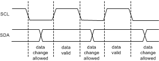 Figure 20. Data Validity Data
A pullup resistor between the VIO line of the controller and SDA must be greater than [(VIO – VOL) / 3 mA] to meet the VOL requirement on SDA. Using a larger pullup resistor results in lower switching current with slower edges, while using a smaller pullup resistor results in higher switching currents with faster edges.
7.5.2.2 Start and Stop Conditions
START and STOP conditions classify the beginning and the end of the I2C session. A START condition is defined as the SDA signal transitioning from HIGH to LOW while SCL line is HIGH. A STOP condition is defined as the SDA transitioning from LOW to HIGH while SCL is HIGH. The I2C master always generates START and STOP conditions. The I2C bus is considered busy after a START condition and free after a STOP condition. During data transmission, the I2C master can generate repeated START conditions. First START and repeated START conditions are equivalent, function-wise.
 Figure 21. Start and Stop Conditions
7.5.2.3 Transferring Data
Every byte put on the SDA line must be eight bits long, with the most significant bit (MSB) transferred first. Each byte of data has to be followed by an acknowledge bit. The acknowledge related clock pulse is generated by the master. The master releases the SDA line (HIGH) during the acknowledge clock pulse. The LM36011 pulls down the SDA line during the 9th clock pulse, signifying an acknowledge. The LM36011 generates an acknowledge after each byte is received. There is no acknowledge created after data is read from the device.
After the START condition, the I2C master sends a chip address. This address is seven bits long followed by an eighth bit which is a data direction bit (R/W). The LM36011 7-bit address is 0x64. For the eighth bit, a 0 indicates a WRITE, and a 1 indicates a READ. The second byte selects the register to which the data is written. The third byte contains data to write to the selected register.
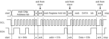 Figure 22. Write Cycle W = Write (SDA = 0) R = Read (SDA = 1) Ack = Acknowledge
 (SDA Pulled Down by Either Master or Slave) ID = Chip Address, 64h for LM36011
7.5.2.4 I2C-Compatible Chip Address
The device address for the LM36011 is 1100100 (0x64). After the START condition, the I2C-compatible master sends the 7-bit address followed by an eighth read or write bit (R/W). R/W = 0 indicates a WRITE and R/W = 1 indicates a READ. The second byte following the device address selects the register address to which the data is written. The third byte contains the data for the selected register.
 Figure 23. I2C-Compatible Chip Address
7.6 Register Descriptions
| REGISTER NAME | INTERNAL HEX ADDRESS | POWER ON/RESET VALUE |
|---|---|---|
| LM36011 | ||
| Enable Register | 0x01 | 0x20 |
| Configuration Register | 0x02 | 0x15 |
| LED Flash Brightness Register | 0x03 | 0x00 |
| LED Torch Brightness Register | 0x04 | 0x00 |
| Flags Register | 0x05 | 0x00 |
| Device ID Register | 0x06 | 0x01 |
7.6.1 Enable Register (0x01)
| Bit 7 | Bit 6 | Bit 5 | Bit 4 | Bit 3 | Bit 2 | Bit 1 | Bit 0 |
|---|---|---|---|---|---|---|---|
| RFU | RFU | RFU | IVFM Enable
0 = Disabled (Default) 1 = Enabled |
Strobe Type
0 = Level Triggered (Default) 1 = Edge Triggered |
Strobe Enable
0 = Disabled (Default ) 1 = Enabled |
Mode Bits: M1, M0
00 = Standby (Default) 01 = IR Drive 10 = Torch 11 = Flash |
|
NOTE
Edge strobe mode is not valid in IR MODE. Switching between level and edge strobe types while the device is enabled is not recommended.
In edge or level strobe mode, TI recommends that the trigger pulse width be set greater than 1 ms to ensure proper turn-on of the device.
7.6.2 Configuration Register (0x02)
| Bit 7 | Bit 6 | Bit 5 | Bit 4 | Bit 3 | Bit 2 | Bit 1 | Bit 0 |
|---|---|---|---|---|---|---|---|
| IVFM Levels (IVFM-D)
000 = 2.9 V (Default) 001 = 3 V 010 = 3.1 V 011 = 3.2 V 100 = 3.3 V 101 = 3.4 V 110 = 3.5 V 111 = 3.6 V |
Flash Time-out Duration
0000 = 40 ms 0001 = 80 ms 0010 = 120 ms 0011 = 160 ms 0100 = 200 ms 0101 = 240 ms 0110 = 280 ms 0111 = 320 ms 1000 = 360 ms 1001 = 400 ms 1010 = 600 ms (Default) 1011 = 800 ms 1100 = 1000 ms 1101 = 1200 ms 1110 = 1400 ms 1111 = 1600 ms |
Torch Ramp
0 = No Ramp 1 = 1 ms (default) |
|||||
NOTE
On the LM36011, special care must be taken with regards to thermal management when using time-out values greater than 500 ms. Depending on the PCB layout, input voltage, and output current, it is possible to have the internal thermal shutdown circuit trip prior to reaching the desired flash time-out value.
7.6.3 LED Flash Brightness Register (0x03)
| Bit 7 | Bit 6 | Bit 5 | Bit 4 | Bit 3 | Bit 2 | Bit 1 | Bit 0 |
|---|---|---|---|---|---|---|---|
| Thermal Current Scale-Back
0 = Disabled 1 = Enabled (default) If enabled, the LED current shifts to torch current level if TJ reaches 125 °C |
LED Flash Brightness Level
0000000 = 11 mA (Default) ....................... 00010101 (0x15) = 0.257 A ....................... 0111111 (0x3F) = 0.75 A ....................... 0101111 (0x5F) = 1.03 A ....................... 01100110 (0x66) = 1.2 A ....................... 1111111 (0x7F) = 1.5 A |
||||||
7.6.4 LED Torch Brightness Register (0x04)
| Bit 7 | Bit 6 | Bit 5 | Bit 4 | Bit 3 | Bit 2 | Bit 1 | Bit 0 |
|---|---|---|---|---|---|---|---|
| RFU | LED Torch Brightness Levels
0000000 = 2.4 mA (Default) ....................... 00010101 (0x15) = 64 mA ....................... 0111111 (0x3F) = 188 mA ....................... 0101111 (0x5F) = 258 mA ....................... 01100110 (0x66) = 302 mA ....................... 1111111 (0x7F) = 376 mA |
||||||
7.6.5 Flags Register (0x05)
| Bit 7 | Bit 6 | Bit 5 | Bit 4 | Bit 3 | Bit 2 | Bit 1 | Bit 0 |
|---|---|---|---|---|---|---|---|
| RFU | IVFM Trip Flag | VLED Short Fault | RFU | Thermal Current Scale-back (TSB) Flag | Thermal Shutdown (TSD) Fault | UVLO Fault | Flash Time-Out Flag |
7.6.6 Device ID and RESET Register (0x06)
| Bit 7 | Bit 6 | Bit 5 | Bit 4 | Bit 3 | Bit 2 | Bit 1 | Bit 0 |
|---|---|---|---|---|---|---|---|
| Software RESET
0 = Normal (default) 1 = Force device RESET |
RFU | Device ID
000 |
Silicon Revision Bits
001 |
||||
8 Applications and Implementation
NOTE
Information in the following applications sections is not part of the TI component specification, and TI does not warrant its accuracy or completeness. TI’s customers are responsible for determining suitability of components for their purposes. Customers should validate and test their design implementation to confirm system functionality.
8.1 Application Information
The LM36011 can drive a flash LED at currents up to 1.5 A. .
8.2 Typical Application
 Figure 24. LM36011 Typical Application
8.2.1 Design Requirements
Example requirements based on default register values:
Table 1. Design Parameters
| DESIGN PARAMETER | EXAMPLE VALUE |
|---|---|
| Input voltage range | 2.5 V to 5.5 V |
| Brightness control | I2C Register |
| LED configuration | 1 flash LED |
| Flash brightness | 1.5-A maximum current |
8.2.2 Detailed Design Procedure
8.2.2.1 Thermal Performance
Output power is limited by two things: the ambient temperature, and the maximum power dissipation in the package. If the die temperature of the device is below the absolute maximum rating of 125°C, the maximum output power can be over 6 W. However, any appreciable output current causes the internal power dissipation to increase and therefore increase the die temperature. Any circuit configuration must ensure that the die temperature remains below 125°C taking into account the ambient temperature derating. The thermal scale-back protection (TSB) helps ensure that temperature requirement is held valid. If the TSB feature is disabled, thermal shutdown (TSD) is the next level of protection for the device, which is set to 150°C. This mechanism cannot be disabled, and operation of the device above 125°C is not ensured by the electrical specification.
The device power dissipation equals:

Use Equation 2 to calculate the junction temperature (TJ) of the device:

Note that these equations only provide approximation of the junction temperature and do not take into account thermal time constants, which play a large role in determining maximum deliverable output power and flash durations.
8.2.2.2 Input Capacitor Selection
Choosing the correct size and type of input capacitor helps minimize noise on the input pin of the boost converter that can feed through and disrupt internal analog signals. In the typical application circuit a 10-µF ceramic input capacitor works well. It is important to place the input capacitor as close as possible to the LM36011 input (IN) pin. This reduces the series resistance and inductance that can inject noise into the device. Table 2 lists various input capacitors recommended for use with the LM36011.
Table 2. Recommended InputCapacitors (X5R/X7R Dielectric)
| MANUFACTURER | PART NUMBER | VALUE | CASE SIZE | VOLTAGE RATING |
|---|---|---|---|---|
| TDK Corporation | C1608JB0J106M | 10 µF | 0603 (1.6 mm × 0.8 mm × 0.8 mm) | 6.3 V |
| TDK Corporation | C2012JB1A106M | 10 µF | 0805 (2 mm × 1.25 mm × 1.25 mm) | 10 V |
| Murata | GRM188R60J106M | 10 µF | 0603 (1.6 mm × 0.8 mm × 0.8 mm) | 6.3 V |
| Murata | GRM21BR61A106KE19 | 10 µF | 0805 (2 mm × 1.25 mm × 1.25 mm) | 10 V |
8.2.3 Application Curves
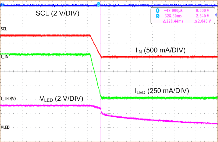
TA = 25°C, VIN = 3.6 V, CIN = 10 µF, VLED = 3.4 V, Flash Time-out = 320 ms and Thermal Scale-Back (TSB) disabled, unless otherwise noted.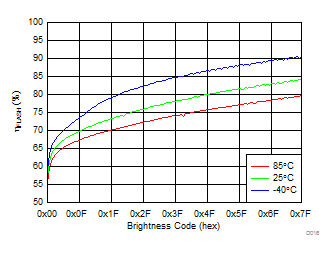
| VIN = 4.0 V |
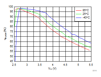
| IFLASH = 1.03 A | ||
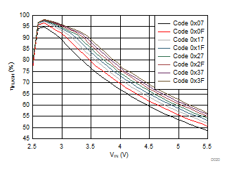
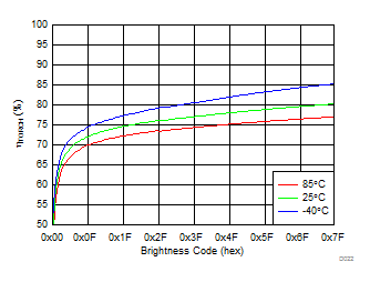
| ITORCH = 258 mA | ||
| Time (200 µs/DIV) | ||
| Mode bits (Reg 0x01 bit[1:0]) = 11 (Flash mode) |
| Time (2 ms/DIV) |
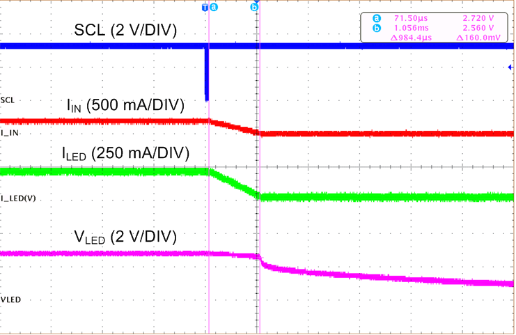
| Time (1 ms/DIV) | ||
| Mode bits (Reg 0x01 bit[1:0]) = 00 (Standby mode) |
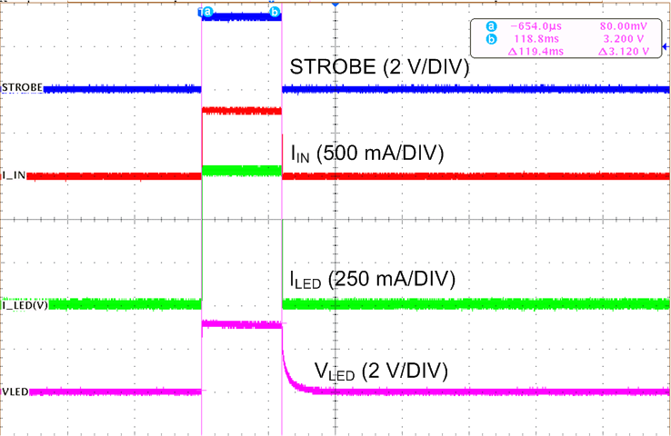
| Time (100 ms/DIV) | ||
| STROBE Enabled (Reg 0x01 bit[2] = 1) | ||
| Level Triggered (Reg 0x01 bit[3] = 0) | ||
| Strobe pulse = 100 ms |
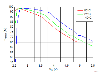
| IFLASH = 1.5 A | ||
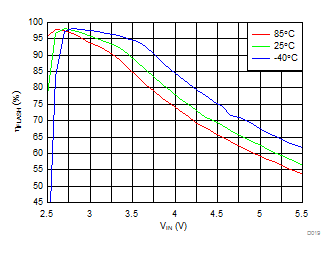
| IFLASH = 0.75 A | ||
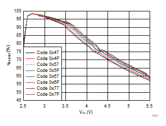
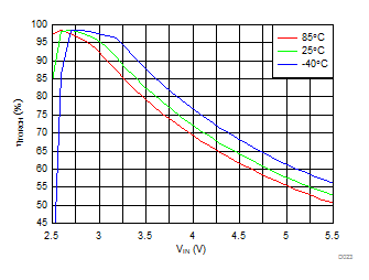
| ITORCH = 376 mA | ||
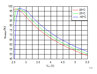
| ITORCH = 188 mA |
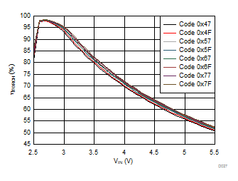
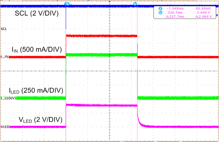
| Time (100 ms/DIV) | ||
| Flash Time-out (Reg 0x02 bits[4:1]) = 0111 (320 ms) |
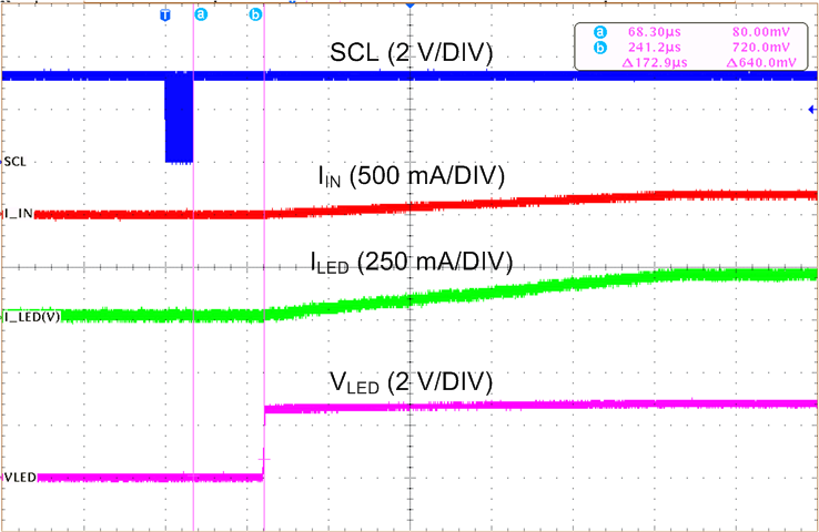
| Time (200 µs/DIV) | ||
| Mode bits (Reg 0x01 bit[1:0]) = 10 (Torch mode) |
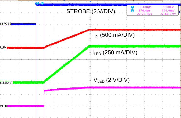
| Time (400 µs/DIV) | ||
| STROBE Enabled (Reg 0x01 bit[2] = 1) |
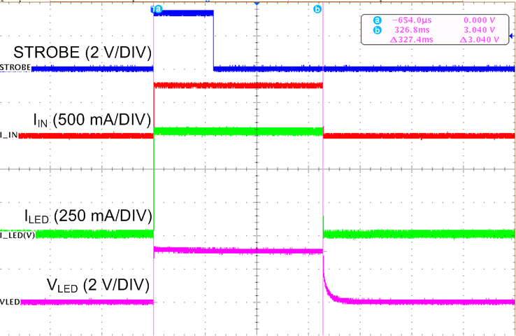
| Time (100 ms/DIV) | ||
| STROBE Enabled (Reg 0x01 bit[2] = 1) | ||
| Edge Triggered (Reg 0x01 bit[3] = 1) | ||
| Flash Time-out = 320 ms |
9 Power Supply Recommendations
The LM36011 is designed to operate from an input voltage supply range between 2.5 V and 5.5 V. This input supply must be well regulated and capable to supply the required input current. If the input supply is located far from the LM36011 additional bulk capacitance may be required in addition to the ceramic bypass capacitors.