-
LM43603-Q1 3.5-V to 36-V, 3-A Synchronous Step-Down Voltage Converter
- 1 Features
- 2 Applications
- 3 Description
- 4 Revision History
- 5 Pin Configuration and Functions
- 6 Specifications
-
7 Detailed Description
- 7.1 Overview
- 7.2 Functional Block Diagram
- 7.3
Feature Description
- 7.3.1 Fixed Frequency Peak Current Mode Controlled Step-Down Regulator
- 7.3.2 Light Load Operation
- 7.3.3 Adjustable Output Voltage
- 7.3.4 Enable (EN)
- 7.3.5 VCC, UVLO, and BIAS
- 7.3.6 Soft-Start and Voltage Tracking (SS/TRK)
- 7.3.7 Switching Frequency (RT) and Synchronization (SYNC)
- 7.3.8 Minimum ON Time, Minimum OFF Time and Frequency Foldback at Dropout Conditions
- 7.3.9 Internal Compensation and CFF
- 7.3.10 Bootstrap Voltage (BOOT)
- 7.3.11 Power Good (PGOOD)
- 7.3.12 Overcurrent and Short-Circuit Protection
- 7.3.13 Thermal Shutdown
- 7.4 Device Functional Modes
-
8 Applications and Implementation
- 8.1 Application Information
- 8.2
Typical Applications
- 8.2.1 Design Requirements
- 8.2.2
Detailed Design Procedure
- 8.2.2.1 Custom Design With WEBENCH® Tools
- 8.2.2.2 Output Voltage Setpoint
- 8.2.2.3 Switching Frequency
- 8.2.2.4 Input Capacitors
- 8.2.2.5 Inductor Selection
- 8.2.2.6 Output Capacitor Selection
- 8.2.2.7 Feed-Forward Capacitor
- 8.2.2.8 Bootstrap Capacitors
- 8.2.2.9 VCC Capacitor
- 8.2.2.10 BIAS Capacitors
- 8.2.2.11 Soft-Start Capacitors
- 8.2.2.12 Undervoltage Lockout Setpoint
- 8.2.2.13 PGOOD
- 8.2.3 Application Performance Curves
- 9 Power Supply Recommendations
- 10Layout
- 11Device and Documentation Support
- 12Mechanical, Packaging, and Orderable Information
- IMPORTANT NOTICE
Package Options
Mechanical Data (Package|Pins)
- PWP|16
Thermal pad, mechanical data (Package|Pins)
- PWP|16
Orderable Information
LM43603-Q1 3.5-V to 36-V, 3-A Synchronous Step-Down Voltage Converter
1 Features
- Qualified for Automotive Applications
- AEC-Q100 Qualified With the Following Results:
- Device Temperature Grade 1: –40°C to +125°C Operating Junction Temperature
- 27-µA Quiescent Current in Regulation
- High Efficiency at Light Load (DCM and PFM)
- Meets EN55022/CISPR 22 EMI Standards
- Integrated Synchronous Rectification
- Adjustable Frequency Range: 200 kHz to 2.2 MHz (500 kHz default)
- Frequency Synchronization to External Clock
- Internal Compensation
- Stable With Almost any Combination of Ceramic, Polymer, Tantalum, and Aluminum Capacitors
- Power-Good Flag
- Soft Start into a Pre-Biased Load
- Internal Soft Start: 4.1 ms
- Extendable Soft-Start Time by External Capacitor
- Output Voltage Tracking Capability
- Precision Enable to a Program System UVLO
- Output Short Circuit Protection with Hiccup Mode
- Overtemperature Thermal Shutdown Protection
- Create a Custom Design Using the LM43603-Q1 With the WEBENCH® Power Designer
2 Applications
3 Description
The LM43603-Q1 regulator is an easy-to-use synchronous step-down DC-DC converter capable of driving up to 3 A of load current from an input voltage ranging from 3.5 V to 36 V (42 V absolute maximum). The LM43603-Q1 provides exceptional efficiency, output accuracy, and dropout voltage in a very small solution size. An extended family is available in 0.5-A, 1-A, and 2-A load current options in pin-to-pin compatible packages. Peak current mode control is employed to achieve simple control loop compensation and cycle-by-cycle current limiting. Optional features such as programmable switching frequency, synchronization, power-good flag, precision enable, internal soft-start, extendable soft start, and tracking provide a flexible and easy to use platform for a wide range of applications. Discontinuous conduction and automatic frequency modulation at light loads improve light load efficiency. The family requires few external components and pin arrangement allows simple, optimum PCB layout. Protection features include thermal shutdown, VCC undervoltage lockout, cycle-by-cycle current limit, and output short circuit protection. The LM43603-Q1 device is available in the HTSSOP (PWP) 16-pin leaded package (6.6 mm × 5.1 mm × 1.2 mm). The LM43603A-Q1 version is optimized for PFM operation and recommended for new design. The device is pin-to-pin compatible with LM4360x and LM4600x family.
Device Information
| PART NUMBER | PACKAGE | BODY SIZE |
|---|---|---|
| LM43603-Q1 | HTSSOP (16) | 6.60 mm × 5.10 mm |
| LM43603A-Q1 | HTTSOP (16) | 6.60 mm × 5.10 mm |
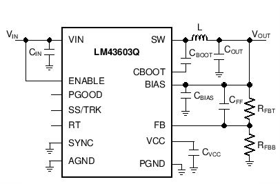
Simplified Schematic
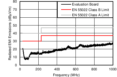
Radiated Emission Graph
12 VIN to 3.3 VOUT, FS = 500 kHz, IOUT = 3 A
4 Revision History
Changes from B Revision (April 2017) to C Revision
- Added top navigator icon for TI reference design Go
- Changed MAX value for VBIAS rising threshold from "3.15" to "3.18" V Go
Changes from A Revision (May 2015) to B Revision
- Added links for Webench Go
- Added LM43603A Device InformationGo
- Added Maximum Operating Junction Temperature Go
- Added standard FN1 to Thermal Information Go
- Updating the RPGOOD value on EN = 3.3V and EN = 0V Go
- Updating Figure 11 to match Figure 87 Go
- Updating EN Falling Threshold CurveGo
- Updating EN Rising Threshold Curve Go
- Updating EN Hysteresis Curve Go
- Changed Figure 33 into conducted EMI CurveGo
- Replaced last few sentences of Application Information due to new Webench contentGo
- Added Equation 25Go
- Added Equation 26Go
- Added Figure 73 to Figure 78. Application Performance Curves for VOUT = 5 V, Fs = 500 kHz. Go
- Changed Figure 86Go
- Changed Figure 87 Go
Changes from * Revision (April 2015) to A Revision
- Changed device from Product Preview to Production Data Go
- Deleted "Super-AM Band"Go
- Added "BIAS pin voltage should never exceed VIN" to BIAS pin descriptionGo
- Added "of 10000 hours" to Ab Max FN 2Go
- Changed info in Vfb rows; in ILKG-FB changed value of from FB=1.011 V to 1.015 VGo
- Changed VFB = 1.011 V to VFB = 1.015 VGo
5 Pin Configuration and Functions
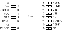
Pin Functions
| PIN | DESCRIPTION | ||
|---|---|---|---|
| NAME | NO. | TYPE(1) | |
| SW | 1, 2 | P | Switching output of the regulator. Internally connected to both power MOSFETs. Connect to power inductor. |
| CBOOT | 3 | P | Boot-strap capacitor connection for high-side driver. Connect a high quality 470-nF capacitor from CBOOT to SW. |
| VCC | 4 | P | Internal bias supply output for bypassing. Connect bypass capacitor from this pin to AGND. Do not connect external loading to this pin. Never short this pin to ground during operation. |
| BIAS | 5 | P | Optional internal LDO supply input. To improve efficiency, TI recommends tying to VOUT when 3.3 V ≤ VOUT ≤ 28 V, or tie to an external 3.3 V or 5 V rail if available. When used, place a bypass capacitor (1 to 10 µF) from this pin to ground. Tie to ground when not in use. Do not float. BIAS pin voltage should never exceed VIN. |
| SYNC | 6 | A | Clock input to synchronize switching action to an external clock. Use proper high-speed termination to prevent ringing. Connect to ground if not used. Do not float. |
| RT | 7 | A | Connect a resistor RT from this pin to AGND to program switching frequency. Leave floating for 500 kHz default switching frequency. |
| PGOOD | 8 | A | Open drain output for power-good flag. Use a 10-kΩ to 100-kΩ pullup resistor to logic rail or other DC voltage no higher than 12 V. |
| FB | 9 | A | Feedback sense input pin. Connect to the midpoint of feedback divider to set VOUT. Do not short this pin to ground during operation. |
| AGND | 10 | G | Analog ground pin. Ground reference for internal references and logic. Connect to system ground. |
| SS/TRK | 11 | A | Soft-start control pin. Leave floating for internal soft-start slew rate. Connect to a capacitor to extend soft start time. Connect to external voltage ramp for tracking. |
| EN | 12 | A | Enable input to the internal LDO and regulator. High = ON and low = OFF. Connect to VIN, or to VIN through resistor divider,or to an external voltage or logic source. Do not float. |
| VIN | 13,14 | P | Supply input pins to internal LDO and high side power FET. Connect to power supply and bypass capacitors CIN. Path from VIN pin to high frequency bypass CIN and PGND must be as short as possible. |
| PGND | 15,16 | G | Power ground pins, connected internally to the low side power FET. Connect to system ground, PAD, AGND, ground pins of CIN and COUT. Path to CIN must be as short as possible. |
| PAD | - | - | Low impedance connection to AGND. Connect to PGND on PCB. Major heat dissipation path of the die. Must be used for heat sinking to ground plane on PCB. |
6 Specifications
6.1 Absolute Maximum Ratings
over the recommended operating junction temperature (TJ) range of -40°C to +125°C(1)| PARAMETER | MIN | MAX | UNIT | |
|---|---|---|---|---|
| Input voltages | VIN to PGND | –0.3 | 42(2) | V |
| EN to PGND | –0.3 | VIN + 0.3 | ||
| FB, RT, SS/TRK to AGND | –0.3 | 3.6 | ||
| PGOOD to AGND | –0.3 | 15 | ||
| SYNC to AGND | –0.3 | 5.5 | ||
| BIAS to AGND | –0.3 | 30 or VIN(3) | ||
| AGND to PGND | –0.3 | 0.3 | ||
| Output voltages | SW to PGND | –0.3 | VIN + 0.3 | V |
| SW to PGND less than 10-ns transients | –3.5 | 42 | ||
| CBOOT to SW | –0.3 | 5.5 | ||
| VCC to AGND | –0.3 | 3.6 | ||
| Storage temperature, Tstg | –65 | 150 | °C | |
| Operating junction temperature | –40 | 150 | °C | |
6.2 ESD Ratings
| VALUE | UNIT | |||
|---|---|---|---|---|
| V(ESD) | Electrostatic discharge | Human-body model (HBM), per AEC Q100-002(1) | ±2000 | V |
| Charged-device model (CDM), per AEC Q100-011 | ±750 | |||
6.3 Recommended Operating Conditions
over the recommended operating junction temperature (TJ) range of –40°C to +125°C (1)| PARAMETER | MIN | MAX | UNIT | |
|---|---|---|---|---|
| Input voltages | VIN to PGND | 3.5 | 36 | V |
| EN | –0.3 | VIN | ||
| FB | –0.3 | 1.1 | ||
| PGOOD | –0.3 | 12 | ||
| BIAS input not used | –0.3 | 0.3 | ||
| BIAS input used | 3.3 | 28 or VIN (2) | ||
| AGND to PGND | –0.1 | 0.1 | ||
| Output voltage | VOUT | 1 | 28 | V |
| Output current | IOUT | 0 | 3 | A |
| Temperature | Operating junction temperature, TJ | –40 | 125 | °C |
6.4 Thermal Information
| THERMAL METRIC(1)(2)(3) | LM43603-Q1 | UNIT | |
|---|---|---|---|
| PWP (HTSSOP) | |||
| 16 PINS | |||
| RθJA | Junction-to-ambient thermal resistance | 38.9(4) | °C/W |
| RθJC (Top) | Junction-to-case (top) thermal resistance | 24.3 | °C/W |
| RθJB | Junction-to-board thermal resistance | 19.9 | °C/W |
| ψJT | Junction-to-top characterization parameter | 0.7 | °C/W |
| ψJB | Junction-to-board characterization parameter | 19.7 | °C/W |
| RθJC(bot) | Junction-to-case (bottom) thermal resistance | 1.7 | °C/W |
6.5 Electrical Characteristics
Limits apply over the recommended operating junction temperature (TJ) range of –40°C to +125°C, unless otherwise stated. Minimum and Maximum limits are specified through test, design or statistical correlation. Typical values represent the most likely parametric norm at TJ = 25°C, and are provided for reference purposes only. Unless otherwise stated, the following conditions apply: VIN = 12 V, VOUT = 3.3 V, FS = 500 kHz.| PARAMETER | CONDITIONS | MIN | TYP | MAX | UNIT | |
|---|---|---|---|---|---|---|
| SUPPLY VOLTAGE (VIN PIN) | ||||||
| VIN-MIN-ST | Minimum input voltage for start-up | 3.8 | V | |||
| ISHDN | Shutdown quiescent current | VEN = 0 V | 1.2 | 3.1 | µA | |
| IQ-NONSW | Operating quiescent current (non-switching) from VIN | VEN = 3.3 V VFB = 1.5 V VBIAS = 3.4 V external |
5 | 10 | µA | |
| IBIAS-NONSW | Operating quiescent current (non-switching) from external VBIAS | VEN = 3.3 V VFB = 1.5 V VBIAS = 3.4 V external |
85 | 130 | µA | |
| IQ-SW | Operating quiescent current (switching) | VEN = 3.3 V IOUT = 0 A RT = open VBIAS = VOUT = 3.3 V RFBT = 1 Meg |
27 | µA | ||
| ENABLE (EN PIN) | ||||||
| VEN-VCC-H | Voltage level to enable the internal LDO output VCC | VENABLE high level | 1.2 | V | ||
| VEN-VCC-L | Voltage level to disable the internal LDO output VCC | VENABLE low level | 0.525 | V | ||
| VEN-VOUT-H | Precision enable level for switching and regulator output: VOUT | VENABLE high level | 2 | 2.20 | 2.42 | V |
| VEN-VOUT-HYS | Hysteresis voltage between VOUT precision enable and disable thresholds | VENABLE hysteresis | –290 | mV | ||
| ILKG-EN | Enable input leakage current | VEN = 3.3 V | 0.85 | 1.75 | µA | |
| INTERNAL LDO (VCC and BIAS PINS) | ||||||
| VCC | Internal LDO output voltage VCC | VIN ≥ 3.8 V | 3.28 | V | ||
| VCC-UVLO | Undervoltage lockout (UVLO) thresholds for VCC | VCC rising threshold | 3.1 | V | ||
| Hysteresis voltage between rising and falling thresholds | –520 | mV | ||||
| VBIAS-ON | Internal LDO input change over threshold to BIAS | VBIAS rising threshold | 2.94 | 3.18 | V | |
| Hysteresis voltage between rising and falling thresholds | -75 | mV | ||||
| VOLTAGE REFERENCE (FB PIN) | ||||||
| VFB | Feedback voltage | TJ = 25 ºC | 1.012 | 1.015 | 1.019 | V |
| TJ = -40 ºC to 125 ºC | 0.999 | 1.015 | 1.032 | |||
| ILKG-FB | Input leakage current at FB pin | FB = 1.015 V | 0.2 | 65 | nA | |
| THERMAL SHUTDOWN | ||||||
| TSD (1) | Thermal shutdown | Shutdown threshold | 160 | ºC | ||
| Recovery threshold | 150 | ºC | ||||
| CURRENT LIMIT AND HICCUP | ||||||
| IHS-LIMIT | Peak inductor current limit | 4.4 | 5.5 | 6.4 | A | |
| ILS-LIMIT | Inductor current valley limit | 2.6 | 3 | 3.3 | A | |
| SOFT START (SS/TRK PIN) | ||||||
| ISSC | Soft-start charge current | 1.25 | 2 | 2.75 | µA | |
| RSSD | Soft-start discharge resistance | UVLO, TSD, OCP, or EN = 0 V | 18 | kΩ | ||
| POWER GOOD (PGOOD PIN) | ||||||
| VPGOOD-HIGH | Power-good flag over voltage tripping threshold | % of FB voltage | 110% | 113% | ||
| VPGOOD-LOW | Power-good flag under voltage tripping threshold | % of FB voltage | 77% | 88% | ||
| VPGOOD-HYS | Power-good flag recovery hysteresis | % of FB voltage | 6% | |||
| RPGOOD | PGOOD pin pulldown resistance when power bad | VEN = 3.3 V | 69 | 150 | Ω | |
| VEN = 0 V | 150 | 350 | ||||
| MOSFETS (2) | ||||||
| RDS-ON-HS | High-side MOSFET ON-resistance | IOUT = 1 A VBIAS = VOUT = 3.3 V |
120 | mΩ | ||
| RDS-ON-LS | Low-side MOSFET ON-resistance | IOUT = 1 A VBIAS = VOUT = 3.3 V |
65 | mΩ | ||
6.6 Timing Requirements
| MIN | NOM | MAX | UNIT | ||
|---|---|---|---|---|---|
| CURRENT LIMIT AND HICCUP | |||||
| NOC | Hiccup wait cycles when LS current limit tripped | 32 | Cycles | ||
| TOC | Hiccup retry delay time | 5.5 | ms | ||
| SOFT START (SS/TRK PIN) | |||||
| TSS | Internal soft-start time when SS pin open circuit | 4.1 | ms | ||
| POWER GOOD (PGOOD PIN) | |||||
| TPGOOD-RISE | Power-good flag rising transition deglitch delay | 220 | µs | ||
| TPGOOD-FALL | Power-good flag falling transition deglitch delay | 220 | µs | ||
6.7 Switching Characteristics
Limits apply over the recommended operating junction temperature (TJ) range of –40°C to +125°C, unless otherwise stated. Minimum and Maximum limits are specified through test, design or statistical correlation. Typical values represent the most likely parametric norm at TJ = 25°C, and are provided for reference purposes only. Unless otherwise stated, the following conditions apply: VIN = 12 V, VOUT = 3.3 V, FS = 500 kHz.| PARAMETER | TEST CONDITIONS | MIN | TYP | MAX | UNIT | |
|---|---|---|---|---|---|---|
| SW (SW PIN) | ||||||
| tON-MIN(1) | Minimum high side MOSFET ON time | 125 | 165 | ns | ||
| tOFF-MIN(1) | Minimum high side MOSFET OFF time | 200 | 250 | ns | ||
| OSCILLATOR (SW and SYNC PINS) | ||||||
| FOSC-DEFAULT | Oscillator default frequency | RT pin open circuit | 425 | 500 | 580 | kHz |
| FADJ | Minimum adjustable frequency | With 1% resistors at RT pin | 200 | kHz | ||
| Maximum adjustable frequency | 2200 | kHz | ||||
| Frequency adjust accuracy | 10% | |||||
| VSYNC-HIGH | Sync clock high level threshold | 2 | V | |||
| VSYNC-LOW | Sync clock low level threshold | 0.4 | V | |||
| DSYNC-MAX | Sync clock maximum duty cycle | 90% | ||||
| DSYNC-MIN | Sync clock minimum duty cycle | 10% | ||||
| TSYNC-MIN | Mininum sync clock ON and OFF time | 80 | ns | |||
6.8 Typical Characteristics
Unless otherwise specified, VIN = 12 V, VOUT = 3.3 V, FS = 500 kHz, L = 6.8 µH and room temperature. See Application Performance Curves for bill of materials for other VOUT and FS combinations.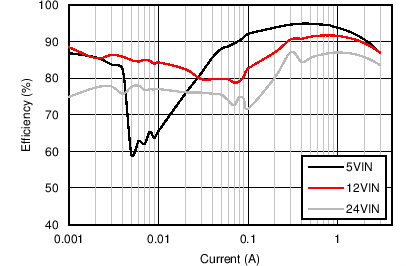
| VOUT = 3.3 V | FS = 500 kHz |
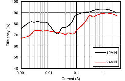
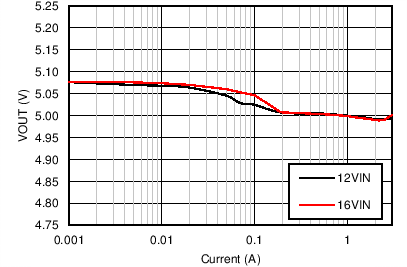
| VOUT = 5 V | FS = 500 kHz |
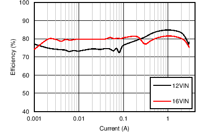
| VOUT = 5 V | FS = 2.2 MHz |
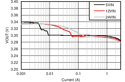
| VOUT = 3.3V | FS = 500 kHz |
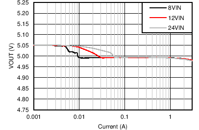
| VOUT = 5 V | FS = 500 kHz |
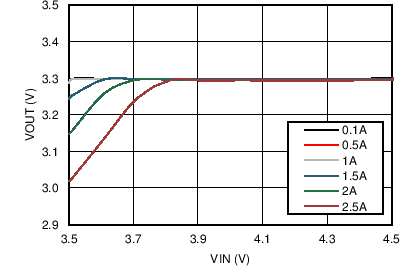
| VOUT = 3.3 V | FS = 500 kHz |
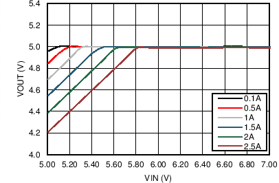
| VOUT = 5 V | FS = 500 kHz |
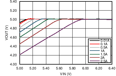
| VOUT = 5 V | FS = 2.2 MHz |
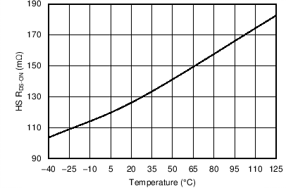 Figure 23. High-Side FET On Resistance vs Junction Temperature
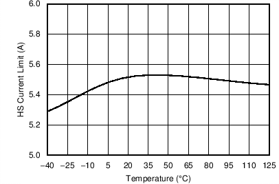 Figure 25. High-Side Current Limit vs Junction Temperature
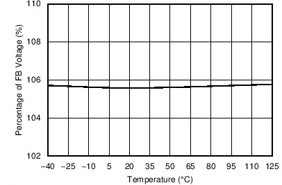 Figure 27. PGOOD OVP Falling Threshold vs Junction Temperature
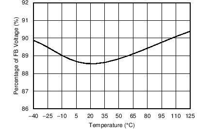 Figure 29. PGOOD UVP Falling Threshold vs Junction Temperature

| VOUT = 3.3 V | FS = 500 kHz | IOUT = 3 A |
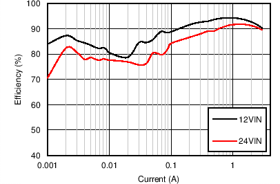
| VOUT = 5V | FS = 200 kHz |
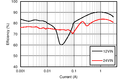
| VOUT = 5 V | FS = 1 MHz |
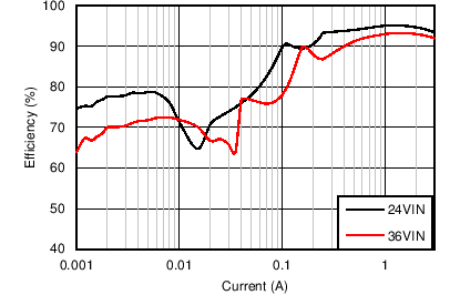
| VOUT = 12 V | FS = 500 kHz |
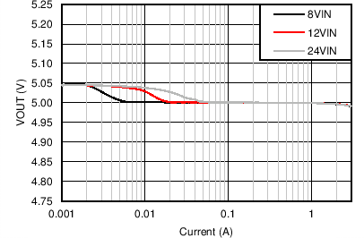
| VOUT = 5 V | FS = 200 kHz |
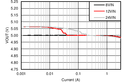
| VOUT = 5 V | FS = 1 MHz |
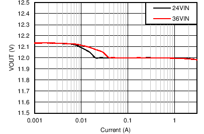
| VOUT = 12 V | FS = 500 kHz |
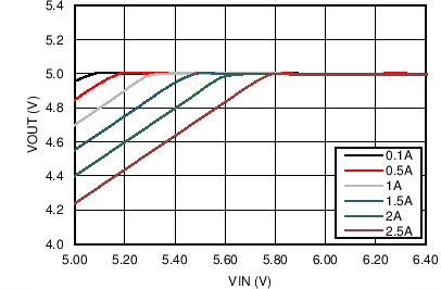
| VOUT = 5 V | FS = 200 kHz |
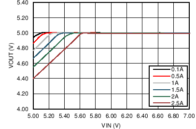
| VOUT = 5 V | FS = 1 MHz |
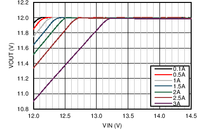
| VOUT = 12 V | FS = 500 kHz |
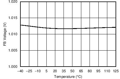 Figure 22. FB Voltage vs Junction Temperature
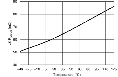 Figure 24. Low-Side FET On Resistance vs Junction Temperature
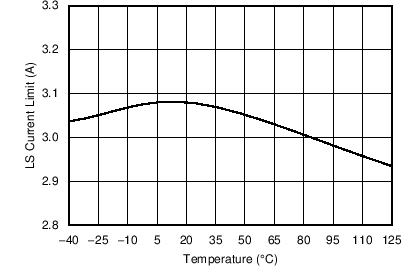 Figure 26. Low-Side Current Limit vs Junction Temperature
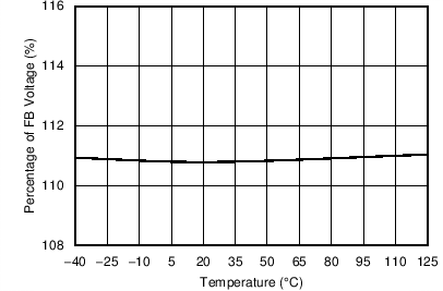 Figure 28. PGOOD OVP Rising Threshold vs Junction Temperature
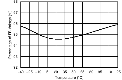 Figure 30. PGOOD UVP Rising Threshold vs Junction Temperature
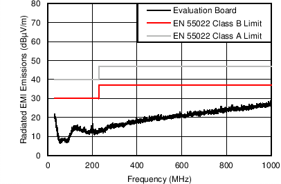
| VOUT = 5 V | FS = 500 kHz | IOUT = 3 A |
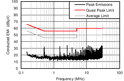
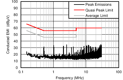
| VOUT = 5 V | FS = 500 kHz | IOUT = 3 A |
| Cd = 47 µF | Lin = 1 µH | CIN4 = 68 µF |
