-
LM48560 Boomer™ Audio Power Amplifier Series High Voltage Class H Ceramic Speaker Driver With Automatic Level Control
- 1 Features
- 2 Applications
- 3 Description
- 4 Revision History
- 5 Pin Configuration and Functions
- 6 Specifications
- 7 Parameter Measurement Information
- 8 Detailed Description
- 9 Application and Implementation
- 10Power Supply Recommendations
- 11Layout
- 12Device and Documentation Support
- 13Mechanical, Packaging, and Orderable Information
- IMPORTANT NOTICE
Package Options
Mechanical Data (Package|Pins)
- YZR|16
Thermal pad, mechanical data (Package|Pins)
Orderable Information
LM48560 Boomer™ Audio Power Amplifier Series High Voltage Class H Ceramic Speaker Driver With Automatic Level Control
1 Features
- Class H Topology
- Integrated Boost Converter
- Bridge-Tied Load (BTL) Output
- Selectable Differential Inputs
- Selectable Control Interfaces
- (Hardware or Software mode)
- I2C Programmable ALC
- Low Supply Current
- Minimum External Components
- Micro-Power Shutdown
- Available in Space-Saving DSBGA Package
- Key Specifications:
- Output Voltage at VDD = 3.6 V,
RL = 1.5 μF + 10 Ω, THD+N ≤ 1%- 30 VP-P (Typical)
- Quiescent Power Supply Current
at 3.6 V (ALC Enabled)- 4 mA (Typical)
- Power Dissipation at 25 VP-P, 1 W (Typical)
- Shutdown Current, 0.1 μA (Typical)
- Output Voltage at VDD = 3.6 V,
2 Applications
- Touch Screen Smart Phones
- Tablet PCs
- Portable Electronic Devices
- MP3 Players
3 Description
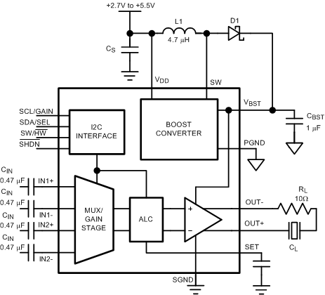
The LM48560 device is a high voltage, high efficiency, Class H driver for ceramic speakers and piezo actuators. The LM48560 device’s Class H architecture offers significant power savings compared to traditional Class AB amplifiers. The device provides 30 VP-P output drive while consuming just 4 mA of quiescent current from a 3.6 V supply.
The LM48560 device features TI’s unique automatic level control (ALC) that provides output limiter functionality. The LM48560 device features two fully differential inputs with separate gain settings, and a selectable control interface. In software control mode, the gain control and device modes are configured through the I2C interface. In hardware control mode, the gain and input mux are configured through a pair of logic inputs.
The LM48560 device has a low power shutdown mode that reduces quiescent current consumption to 0.1 μA. The LM48560 device is available in an ultra-small 16–bump DSBGA package (1.97 mm × 1.97 mm).
Device Information(1)
| PART NUMBER | PACKAGE | BODY SIZE (NOM) |
|---|---|---|
| LM48560 | DSBGA (16) | 1.97 mm × 1.97 mm |
- For all available packages, see the orderable addendum at the end of the data sheet.
Typical Application Circuit

4 Revision History
| Rev | Date | Description |
|---|---|---|
| 1.0 | 08/16/11 | Initial WEB released. |
| 1.01 | 09/21/11 | Input edits under CLASS H OPERATION. |
| 1.02 | 11/01/11 | Edited curves 30150753, 54, 55, 56, and Figure 26 (I2C Read Cycle). |
| 1.03 | 11/10/11 | Edited Figure 26. |
| 1.04 | 07/25/12 | Input texts/limits edits in the EC table. |
| 1.05 | 08/22/12 | Edited Table 1 and Table 2. |
| E | 05/02/2013 | Changed layout of National Data Sheet to TI format. |
| F | 10/21/2015 | Added ESD Ratings table, Feature Description section, Device Functional Modes, Application and Implementation section, Power Supply Recommendations section, Layout section, Device and Documentation Support section, and Mechanical, Packaging, and Orderable Information section. |
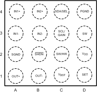
5 Pin Configuration and Functions

Pin Functions
| PIN | I/O | DESCRIPTION | |
|---|---|---|---|
| NO. | NAME | ||
| A1 | OUT+ | O | Amplifier Non-Inverting Output |
| A2 | SGND | — | Amplifier Ground |
| A3 | IN1– | I | Amplifier Inverting Input 1 |
| A4 | IN1+ | I | Amplifier Non-Inverting Input 1 |
| B1 | OUT– | O | Amplifier Inverting Output |
| B2 | SHDN | I | Active Low Shutdown. Connect SHDN to GND to disable device. Connect SHDN to VDD for normal operation |
| B3 | IN2– | I | Amplifier Inverting Input 2 |
| B4 | IN2+ | I | Amplifier Non-Inverting Input 2 |
| C1 | VBST | — | Boost Converter Output |
| C2 | SW/HW | I | Mode Selection Control: SW/HW = 0 → Hardware Mode SW/HW = 1 → Software Mode |
| C3 | SCL/GAIN | I | I2C Serial Clock Input (Software Mode) Gain Select Input (Hardware Mode) see (Table 5) |
| C4 | SDA/SEL | I/O | I2C Serial Data Input (Software Mode) Amplifier Input Select (Hardware Mode) see (Table 5) |
| D1 | SET | — | ALC Timing Input |
| D2 | VDD | — | Power Supply |
| D3 | SW | — | Boost Converter Switching Node |
| D4 | PGND | — | Boost Converter Ground |
6 Specifications
6.1 Absolute Maximum Ratings
over operating free-air temperature range (unless otherwise noted)(1)| MIN | MAX | UNIT | |||
|---|---|---|---|---|---|
| VDD | Supply voltage(2) | 6 | V | ||
| SW | Voltage | 25 | V | ||
| VBST | Voltage | 21 | V | ||
| Input voltage | –0.3 | VDD 0.3 | V | ||
| Power dissipation(3) | Internally limited | ||||
| TJ | Junction temperature | 150 | °C | ||
| Tstg | Storage temperature | –65 | 150 | °C | |
6.2 ESD Ratings
| VALUE | UNIT | |||
|---|---|---|---|---|
| V(ESD) | Electrostatic discharge | Human-body model (HBM), per ANSI/ESDA/JEDEC JS-001(1) | ±2000 | V |
| Charged-device model (CDM), per JEDEC specification JESD22-C101(2) | ±500 | |||
| Machine Model(3) | ±100 | |||
6.3 Recommended Operating Conditions
over operating free-air temperature range (unless otherwise noted)| MIN | NOM | MAX | UNIT | ||
|---|---|---|---|---|---|
| TA | Operating free-air temperature | –40 | 85 | °C | |
| VDD | Supply voltage | 2.7 | 5.5 | V | |
6.4 Electrical Characteristics VDD = 3.6 V
The following specifications apply for RL = 1.5 μF + 10 Ω, CBST = 1 μF, CIN = 0.47 μF, CSET = 100 nF, AV = 24 dB unless otherwise specified. Limits apply for TA = 25 °C.(2)(1)| PARAMETER | TEST CONDITIONS | MIN (1) | TYP (2) | MAX (1) | UNIT | ||
|---|---|---|---|---|---|---|---|
| VDD | Supply voltage | 2.7 | 5.5 | V | |||
| IDD | Quiescent power supply current | VIN = 0 V, RL = ∞ | |||||
| ALC Enabled | 4 | 6 | mA | ||||
| ALC Disabled | 3.6 | mA | |||||
| PD | Power consumption | VOUT = 25 VP-P, f = 1 kHz | 1 | W | |||
| ISD | Shutdown current | Software Mode | 2.5 | 4.4 | µA | ||
| Hardware Mode | 0.1 | 2 | µA | ||||
| TWU | Wake-up time | From Shutdown | 15 | ms | |||
| VOS | Differential output offset voltage | AV = 24 V | 10 | 90 | mV | ||
| AV = 0 dB (Boost Disabled) | 5 | 20 | mV | ||||
| AV | Gain (Hardware Mode) | IN1 | GAIN = 0 | 0.5 | 0 | 0.5 | dB |
| GAIN = 1 | 5.5 | 6 | 6.5 | ||||
| IN2 | GAIN = 0 | 23.5 | 24 | 24.5 | |||
| GAIN = 1 | 29.5 | 30 | 30.5 | ||||
| Gain (software mode) | Boost Disabled | GAIN1 = 0, GAIN0 = 0 | –0.5 | 0 | 0.5 | dB | |
| GAIN1 = 0, GAIN0 = 1 | 5.5 | 6 | 6.5 | ||||
| GAIN1 = 1, GAIN0 = 0 | 11.5 | 12 | 12.5 | ||||
| GAIN1 = 1, GAIN0 = 1 | 17.5 | 18 | 18.5 | ||||
| Boost Enabled | GAIN1 = 0, GAIN0 = 0 | 20.5 | 21 | 21.5 | dB | ||
| GAIN1 = 0, GAIN0 = 1 | 23.5 | 24 | 24.5 | ||||
| GAIN1 = 1, GAIN0 = 0 | 26.5 | 27 | 27.5 | ||||
| GAIN1 = 1, GAIN0 = 1 | 29.5 | 30 | 30.5 | ||||
| RIN | Gain step size (software mode) | 3 | dB | ||||
| Input resistance | AV | 0 dB | 46 | 50 | 58 | kΩ | |
| 30 dB | 46 | 50 | 58 | ||||
| VOUT | Output voltage | THD+N = 1% | VP-P | ||||
| f | 200 Hz | 25 | 30 | ||||
| 1 kHz | 25 | 30 | |||||
| THD+N | Total harmonic distortion + noise | VOUT = 18 VP-P, f = 1 kHz | 0.08% | ||||
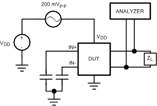
| PSRR | Power supply rejection ratio (Figure 22) |
VDD = 3.6 V + 200 mVP-P sine, Inputs = AC GND | dB | ||||
| fRIPPLE = 217 Hz | 55 | 78 | |||||
| fRIPPLE = 1 kHz | 76 | ||||||
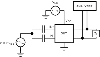
| CMRR | Common mode rejection ratio (Figure 23) |
VCM = 200 mVP-P sine | |||||
| fRIPPLE = 217 Hz | 68 | dB | |||||
| fRIPPLE = 1k Hz | 78 | dB | |||||
| SNR | Signal-to-noise-ratio | Boost Disabled, A-weighted | 107 | dB | |||
| Boost Enabled A-weighted | 98 | dB | |||||
| εOS | Output noise | A-weighted | |||||
| AV | 24 dB | 134 | μVRMS | ||||
| 0 dB (Boost Disabled) | 16 | ||||||
| TA | Attack time | ATK1:ATK0 = 00, CSET = 100 nF | 0.83 | ms | |||
| TR | Release time | RLT1:RLT0 = 00, CSET = 100 nF | 0.5 | s | |||
| fSW | Boost converter switching frequency | 2 | MHz | ||||
| ILIMIT | Boost converter current limit | 1.5 | A | ||||
| VIH | Logic high input threshold | SHDN | 1.4 | V | |||
| VIL | Logic low input threshold | SHDN | 0.5 | V | |||
| IIN | Input leakage current | SHDN | 0.1 | 0.2 | μA | ||
6.5 I2C Interface Characteristics
The following specifications apply for RPU = 1 kΩ to VDD, SW/HW = 1 (Software Mode) unless otherwise specified. Limits apply for TA = 25 °C. (2)(1)| PARAMETER | TEST CONDITIONS | MIN (2) | TYP (2) | MAX (2) | UNIT | |
|---|---|---|---|---|---|---|
| VIH | Logic Input High Threshold | SDA, SCL | 1.1 | V | ||
| VIL | Logic Input Low Threshold | SDA, SCL | 0.5 | V | ||
| SCL Frequency | 400 | kHz | ||||
| t1 | SCL Period | 2.5 | μs | |||
| t2 | SDA Setup Time | 250 | ns | |||
| t3 | SDA Stable Time | 250 | ns | |||
| t4 | Start Condition Time | 250 | ns | |||
| t5 | Stop Condition Time | 250 | ns | |||
 Figure 1. I2C Timing Diagram
 Figure 2. Start and Stop Diagram
6.6 Typical Characteristics
All typical performance curves are taken with conditions seen in Typical Characteristics, unless otherwise specified. Figure 3. THD+N vs Frequency
CL = 0.6 μF, VDD = 3.6 V, Boosted, AV = 24 dB
 Figure 5. THD+N vs Frequency
CL = 1.5 μF, VDD = 3.6 V, Boosted, AV = 24 dB
 Figure 7. THD+N vs Frequency
VDD = 3.6 V, CL = 1 μF, VOUT = 5 VP-P
Unboosted , AV = 0 dB
 Figure 9. Output Voltage vs Frequency
CL = 1.5 μF, THD+N ≤ 1%, Boosted
 Figure 11. THD+N vs Output Voltage
CL = 0.6 μF, VDD = 3.6 V, Boosted, AV = 24 dB
 Figure 13. THD+N vs Output Voltage
CL = 1.5 μF, VDD = 3.6 V, Boosted, AV = 24 dB
 Figure 15. Input Voltage vs Output Voltage
ALC Enabled, AV = 21 dB, VDD = 3.6 V
 Figure 17. Total Power Consumption vs Output Voltage
VDD = 3.6 V, CL = 0.6 μF
 Figure 19. Total Power Consumption vs Output Voltage
VDD = 3.6 V, CL = 1.5 μF
 Figure 21. Power Supply Rejection Ratio vs Frequency
VRIPPLE = 200 mVP-P, VDD = 3.6 V, CL = 1.5 μF
 Figure 4. THD+N vs Frequency
CL = 1 μF, VDD = 3.6 V, Boosted, AV = 24 dB
 Figure 6. THD+N vs Frequency
VDD = 3.6 V, CL = 0.6 μF, VOUT = 5 VP-P
Unboosted, AV = 0 dB
 Figure 8. THD+N vs Frequency
VDD = 3.6 V, CL = 1.5 μF, VOUT = 5 VP-P
Unboosted, AV = 0 dB
 Figure 10. Output Voltage vs Frequency
CL = 1.5 μF, THD+N ≤ 1%, Unboosted
 Figure 12. THD+N vs Output Voltage
CL = 1 μF, VDD = 3.6 V, Boosted, AV = 24 dB
 Figure 14. THD+N vs Output Voltage
CL = 1.5 μF, VDD = 3.6 V, Unboosted, AV = 0 dB
 Figure 16. Supply Current vs Supply Voltage
RL = ∞
 Figure 18. Total Power Consumption vs Output Voltage
VDD = 3.6 V, CL = 1 μF
 Figure 20. Common Mode Rejection Ratio vs Frequency
VCM= 200 mVP-P, CIN = 10 μF, VDD = 3.6 V, CL = 1.5 μF
7 Parameter Measurement Information
 Figure 22. PSRR Test Circuit
 Figure 23. CMRR Test Circuit