-
LM50 and LM50-Q1 SOT-23 Single-Supply Centigrade Temperature Sensor
- 1 Features
- 2 Applications
- 3 Description
- 4 Revision History
- 5 Pin Configuration and Functions
- 6 Specifications
- 7 Detailed Description
- 8 Application and Implementation
- 9 Power Supply Recommendations
- 10Layout
- 11Device and Documentation Support
- 12Mechanical, Packaging, and Orderable Information
- IMPORTANT NOTICE
Refer to the PDF data sheet for device specific package drawings
Mechanical Data (Package|Pins)
- DBZ|3
Thermal pad, mechanical data (Package|Pins)
LM50 and LM50-Q1 SOT-23 Single-Supply Centigrade Temperature Sensor
1 Features
- LM50-Q1 is AEC-Q100 Grade 1 Qualified and is Manufactured on an Automotive Grade Flow
- Calibrated Directly in Degrees Celsius (Centigrade)
- Linear + 10 mV/°C Scale Factor
- ±2°C Accuracy Specified at 25°C
- Specified for Full –40° to 125°C Range
- Suitable for Remote Applications
- Low Cost Due to Wafer-Level Trimming
- Operates From 4.5 V to 10 V
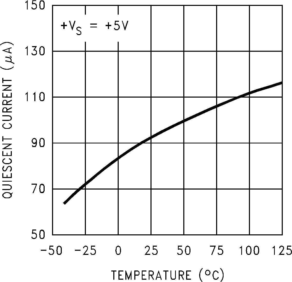
- Less Than 130-µA Current Drain
- Low Self-Heating: Less Than 0.2°C in Still A
- Nonlinearity Less Than 0.8°C Over Temp
- UL Recognized Component
2 Applications
- Automotive
- Computers
- Disk Drives
- Battery Management
- FAX Machines
- Printers
- Portable Medical Instruments
- HVAC
- Power Supply Modules
SPACER
3 Description
The LM50 and LM50-Q1 devices are precision integrated-circuit temperature sensors that can sense a –40°C to 125°C temperature range using a single positive supply. The output voltage of the device is linearly proportional to temperature (10 mV/°C) and has a DC offset of 500 mV. The offset allows reading negative temperatures without the need for a negative supply.
The ideal output voltage of the LM50 or LM50-Q1 ranges from 100 mV to 1.75 V for a –40°C to 125°C temperature range. The LM50 and LM50-Q1 do not require any external calibration or trimming to provide accuracies of ±3°C at room temperature and ±4°C over the full –40°C to 125°C temperature range. Trimming and calibration of the LM50 and LM50-Q1 at the wafer level assure low cost and high accuracy. The linear output, 500 mV offset, and factory calibration of the LM50 and LM50-Q1 simplify the circuitry requirements in a single supply environment where reading negative temperatures is necessary. Because the quiescent current of the LM50 and LM50-Q1 is less than 130 µA, self-heating is limited to a very low 0.2°C in still air.
Device Information(1)
| PART NUMBER | PACKAGE | BODY SIZE (NOM) |
|---|---|---|
| LM50, LM50-Q1 | SOT-23 (3) | 2.92 mm × 1.30 mm |
- For all available packages, see the orderable addendum at the end of the data sheet.
Simplified Schematic
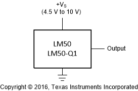
Full-Range Centigrade Temperature Sensor (–40°C to 125°C)

4 Revision History
Changes from F Revision (December 2016) to G Revision
- Changed LMT90 to LM50 in VO description of Equation 1 Go
Changes from E Revision (September 2013) to F Revision
- Added Device Information table, Pin Configuration and Functions section, ESD Ratings table, Detailed Description section, Application and Implementation section, Power Supply Recommendations section, Layout section, Device and Documentation Support section, and Mechanical, Packaging, and Orderable Information sectionGo
- Added Thermal Information tableGo
- Changed Junction-to-ambient, RθJA, value in Thermal Information table From: 450°C/W To: 291.9°C/WGo
- Deleted the Temperature To Digital Converter (Parallel TRI-STATE Outputs for Standard Data Bus to µP Interface) (125°C Full Scale) figureGo
Changes from C Revision (February 2013) to E Revision
- Added LM50-Q1 option throughout documentGo
5 Pin Configuration and Functions

Pin Functions
| PIN | TYPE | DESCRIPTION | |
|---|---|---|---|
| NO. | NAME | ||
| 1 | +VS | Power | Positive power supply pin. |
| 2 | VOUT | Output | Temperature sensor analog output. |
| 3 | GND | Ground | Device ground pin, connected to power supply negative terminal. |
6 Specifications
6.1 Absolute Maximum Ratings
over operating free-air temperature range (unless otherwise noted)(1)| MIN | MAX | UNIT | |
|---|---|---|---|
| Supply voltage | –0.2 | 12 | V |
| Output voltage | –1 | +VS + 0.6 | V |
| Output current | 10 | mA | |
| Maximum junction temperature, TJ | 150 | °C | |
| Storage temperature, Tstg | –65 | 150 | °C |
6.2 ESD Ratings
| VALUE | UNIT | |||
|---|---|---|---|---|
| LM50 | ||||
| V(ESD) | Electrostatic discharge | Human body model (HBM)(1) | ±2000 | V |
| Charged-device model (CDM) | ±750 | |||
| Machine model(1) | ±250 | |||
| LM50-Q1 | ||||
| V(ESD) | Electrostatic discharge | Human-body model (HBM), per AEC Q100-002(2) | ±2000 | V |
| Charged-device model (CDM), per AEC Q100-011 | ±750 | |||
6.3 Recommended Operating Conditions(1)
| MIN | MAX | UNIT | |||
|---|---|---|---|---|---|
| +VS | Supply voltage | 4.5 | 10 | V | |
| TMIN, TMAX | Specified temperature | LM50C, LM50-Q1 | –40 | 125 | °C |
| LM50B | –25 | 100 | |||
| Operating temperature | –40 | 150 | °C | ||
6.4 Thermal Information
| THERMAL METRIC(1) | LM50, LM50-Q1 | UNIT | |
|---|---|---|---|
| DBZ (SOT-23) | |||
| 3 PINS | |||
| RθJA | Junction-to-ambient thermal resistance | 291.9 | °C/W |
| RθJC(top) | Junction-to-case (top) thermal resistance | 114.3 | °C/W |
| RθJB | Junction-to-board thermal resistance | 62.3 | °C/W |
| φJT | Junction-to-top characterization parameter | 7.4 | °C/W |
| φJB | Junction-to-board characterization parameter | 61 | °C/W |
6.5 Electrical Characteristics: LM50B
+VS = 5 V (DC) and ILOAD = 0.5 µA, in the circuit of Figure 12, TA = TJ = 25°C (unless otherwise noted)(1)| PARAMETER | TEST CONDITIONS | MIN | TYP | MAX | UNIT |
|---|---|---|---|---|---|
| Accuracy(2) | TA = 25°C | –2 | 2 | °C | |
| TA = TMAX | –3 | 3 | °C | ||
| TA = TMIN | –3.5 | 3 | °C | ||
| Nonlinearity(3) | TA = TJ = TMIN to TMAX | –0.8 | 0.8 | °C | |
| Sensor gain (average slope) | TA = TJ = TMIN to TMAX | 9.7 | 10.3 | mV/°C | |
| Output resistance | TA = TJ = TMIN to TMAX | 2000 | 4000 | Ω | |
| Line regulation(4) | +VS = 4.5 V to 10 V, TA = TJ = TMIN to TMAX | –1.2 | 1.2 | mV/V | |
| Quiescent current(5) | +VS = 4.5 V to 10 V, TA = TJ = TMIN to TMAX | 180 | µA | ||
| Change of quiescent current | +VS = 4.5 V to 10 V, TA = TJ = TMIN to TMAX | 2 | µA | ||
| Temperature coefficient of quiescent current | TA = TJ = TMIN to TMAX | 1 | µA/°C | ||
| Long term stability(6) | TJ = 125°C, for 1000 hours | ±0.08 | °C |
6.6 Electrical Characteristics: LM50C and LM50-Q1
+VS = 5 V (DC) and ILOAD = 0.5 µA, in the circuit of Figure 12. TA = TJ = 25°C, unless otherwise noted.(1)| PARAMETER | TEST CONDITIONS | MIN | TYP | MAX | UNIT |
|---|---|---|---|---|---|
| Accuracy(1) | TA = 25°C | –3 | 3 | °C | |
| TA = TMAX | –4 | 4 | °C | ||
| TA = TMIN | –4 | 4 | °C | ||
| Nonlinearity(2) | TA = TJ = TMIN to TMAX | –0.8 | 0.8 | °C | |
| Sensor gain(average slope) | TA = TJ = TMIN to TMAX | 9.7 | 10.3 | mV/°C | |
| Output resistance | TA = TJ = TMIN to TMAX | 2000 | 4000 | Ω | |
| Line regulation(3) | +VS = 4.5 V to 10 V, TA = TJ = TMIN to TMAX | –1.2 | 1.2 | mV/V | |
| Quiescent current(4) | +VS = 4.5 V to 10 V, TA = TJ = TMIN to TMAX | 180 | µA | ||
| Change of quiescent current | +VS = 4.5 V to 10 V, TA = TJ = TMIN to TMAX | 2 | µA | ||
| Temperature coefficient of quiescent current | TA = TJ = TMIN to TMAX | 2 | µA/°C | ||
| Long term stability(5) | TJ = 125°C, for 1000 hours | ±0.08 | °C |
6.7 Typical Characteristics
To generate these curves the device was mounted to a printed circuit board as shown in Figure 20.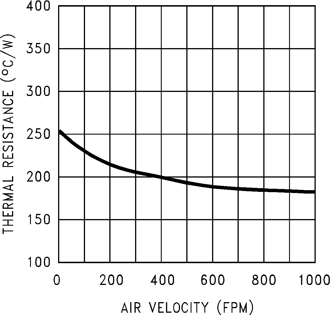 Figure 1. Junction-to-Ambient Thermal Resistance
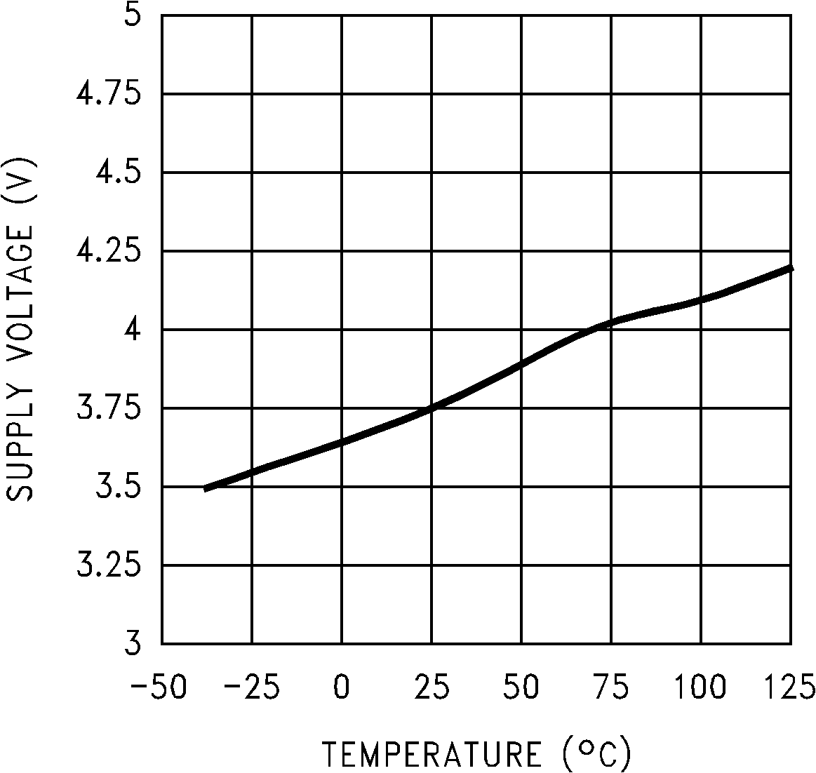 Figure 5. Start-Up Voltage vs Temperature
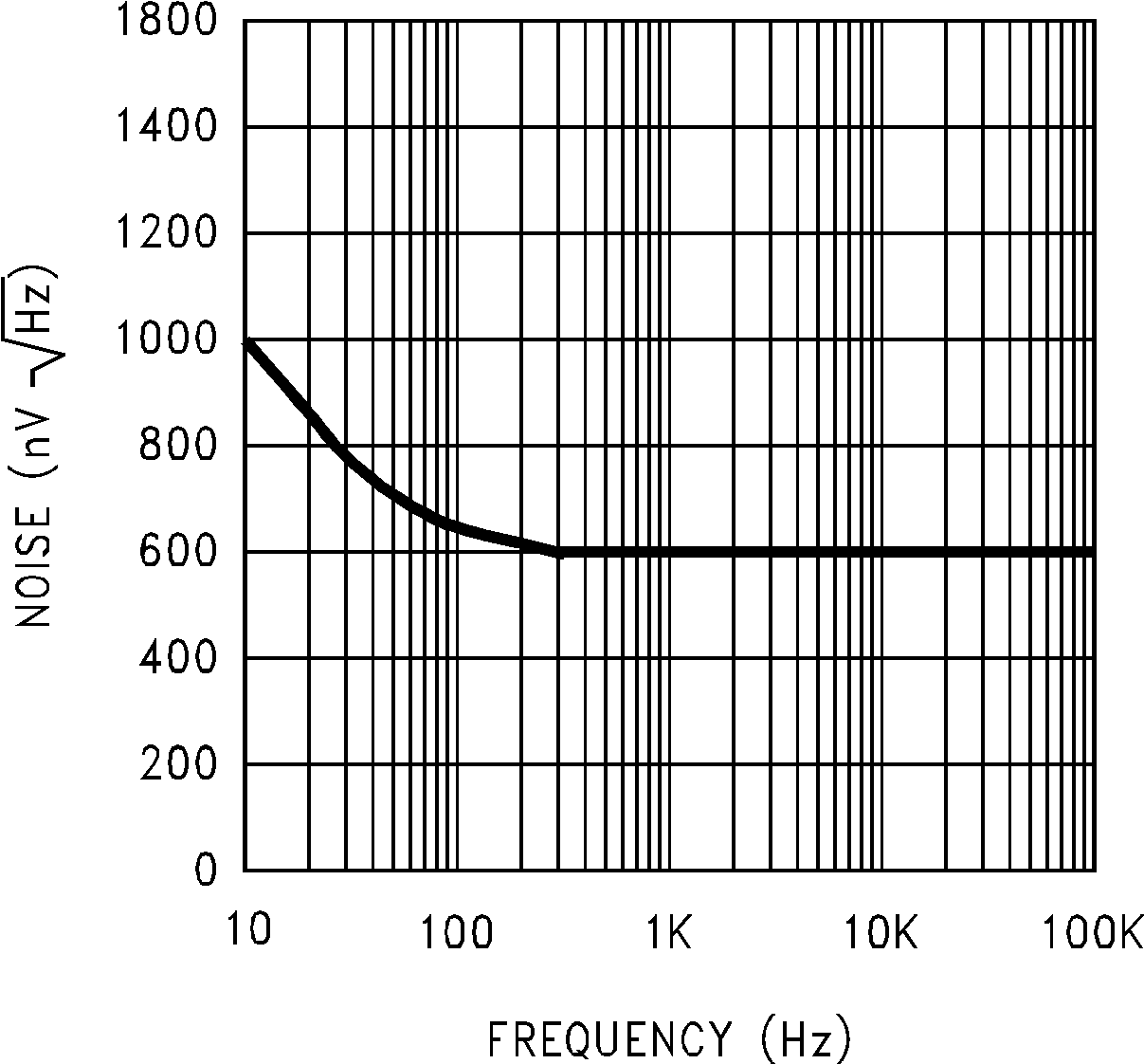 Figure 9. Noise Voltage
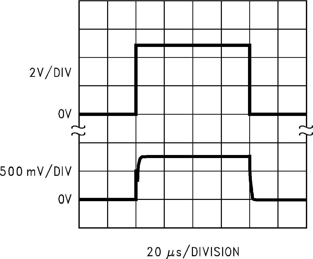 Figure 11. Start-Up Response
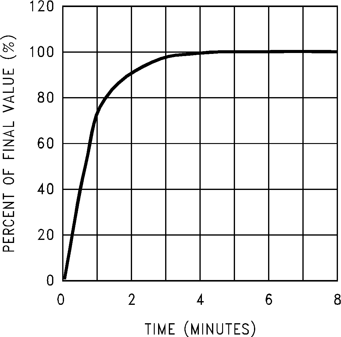
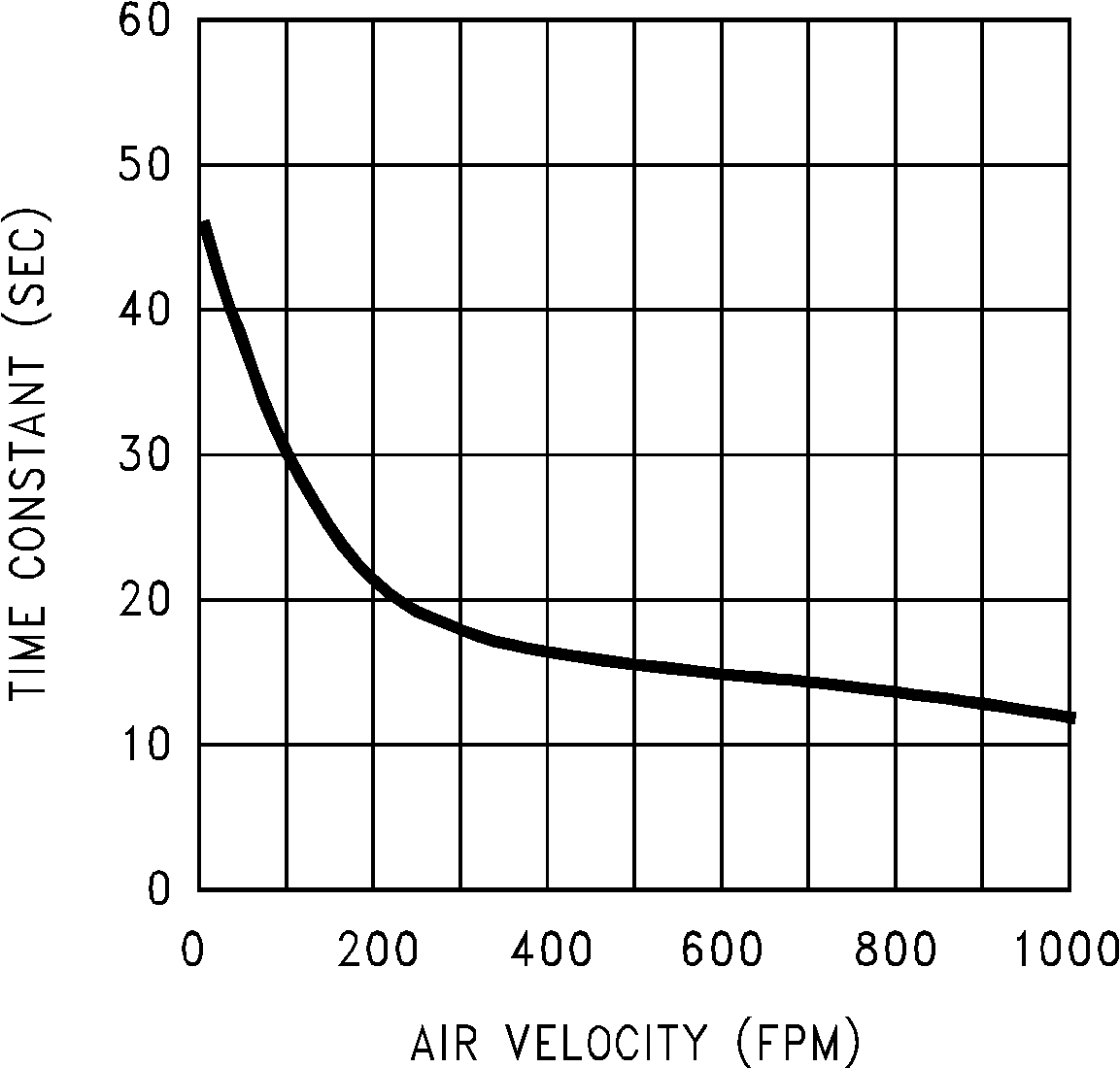 Figure 2. Thermal Time Constant
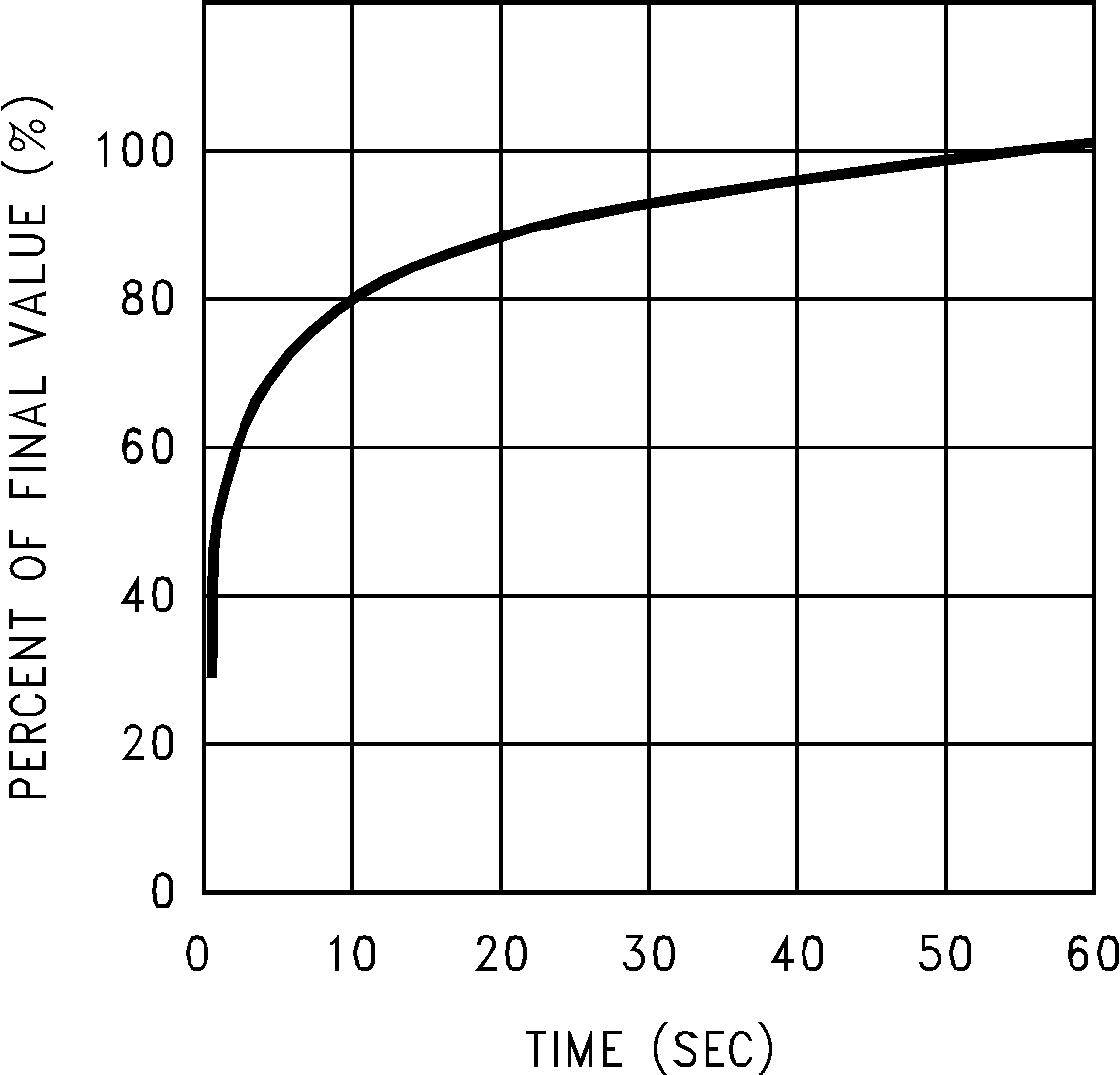
With Heat Sink
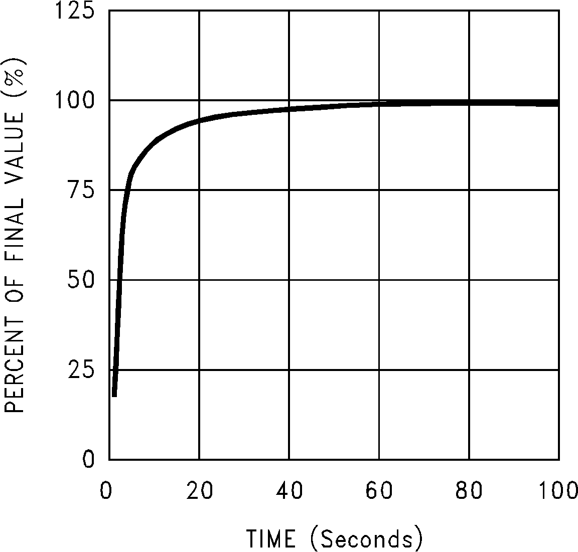 Figure 6. Thermal Response in Still Air Without a Heat Sink
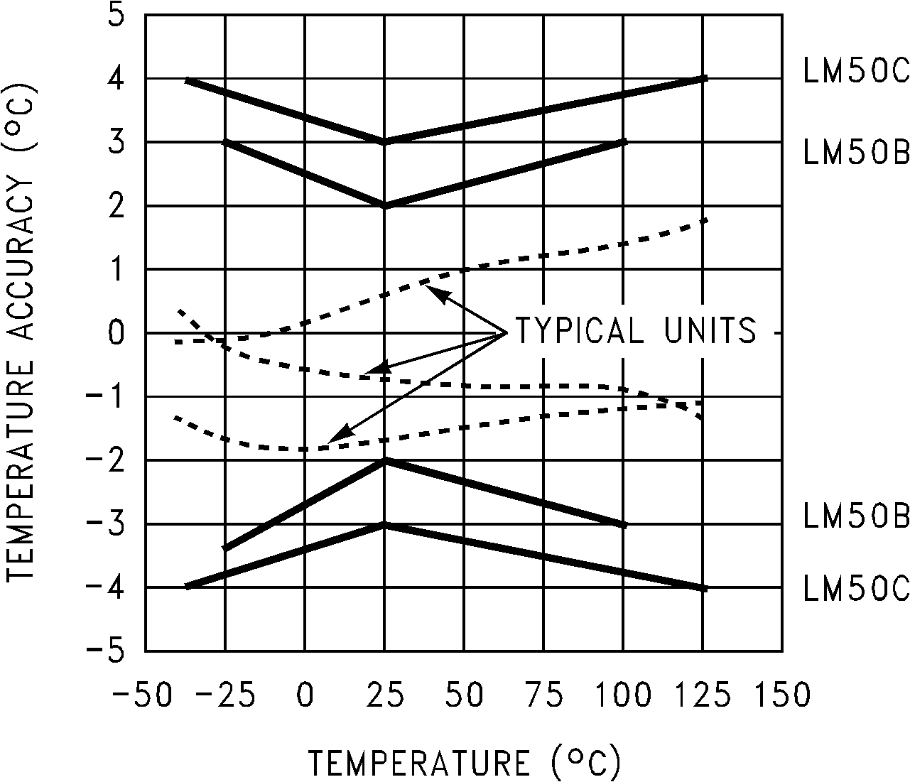
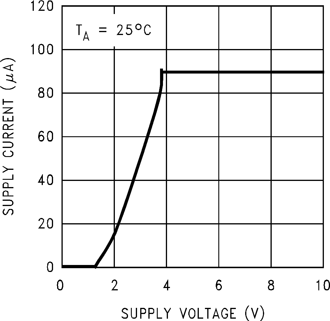 Figure 10. Supply Voltage vs Supply Current
7 Detailed Description
7.1 Overview
The LM50 and LM50-Q1 devices are precision integrated-circuit temperature sensors that can sense a –40°C to 125°C temperature range using a single positive supply. The output voltage of the LM50 and LM50-Q1 has a positive temperature slope of 10 mV/°C. A 500-mV offset is included enabling negative temperature sensing when biased by a single supply.
The temperature-sensing element is comprised of a delta-VBE architecture. The temperature-sensing element is then buffered by an amplifier and provided to the VOUT pin. The amplifier has a simple class A output stage with typical 2-kΩ output impedance as shown in the Functional Block Diagram.
7.2 Functional Block Diagram

7.3 Feature Description
7.3.1 LM50 and LM50-Q1 Transfer Function
The LM50 and LM50-Q1 follow a simple linear transfer function to achieve the accuracy as listed in the Electrical Characteristics: LM50B table and the Electrical Characteristics: LM50C and LM50-Q1 table.
Use Equation 1 to calculate the value of VO.
where
- T is the temperature in °C
- VO is the LM50 output voltage
7.4 Device Functional Modes
The only functional mode of the device has an analog output directly proportional to temperature.
