-
LM555-MIL Timer
- 1 Features
- 2 Applications
- 3 Description
- 4 Revision History
- 5 Pin Configuration and Functions
- 6 Specifications
- 7 Detailed Description
- 8 Application and Implementation
- 9 Power Supply Recommendations
- 10Layout
- 11Device and Documentation Support
- 12Mechanical, Packaging, and Orderable Information
- IMPORTANT NOTICE
Package Options
Mechanical Data (Package|Pins)
- YS|0
Thermal pad, mechanical data (Package|Pins)
Orderable Information
LM555-MIL Timer
1 Features
- Direct Replacement for SE555/NE555
- Timing from Microseconds through Hours
- Operates in Both Astable and Monostable Modes
- Adjustable Duty Cycle
- Output Can Source or Sink 200 mA
- Output and Supply TTL Compatible
- Temperature Stability Better than 0.005% per °C
- Normally On and Normally Off Output
- Available in 8-pin VSSOP Package
2 Applications
- Precision Timing
- Pulse Generation
- Sequential Timing
- Time Delay Generation
- Pulse Width Modulation
- Pulse Position Modulation
- Linear Ramp Generator
3 Description
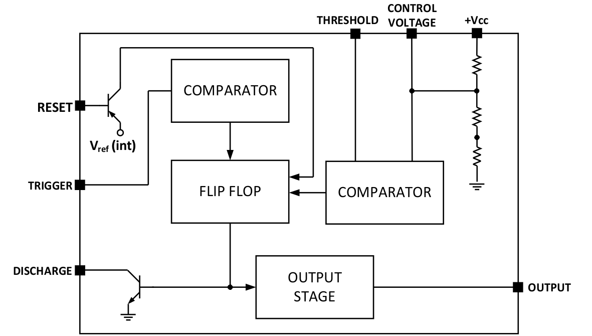
The LM555-MIL is a highly stable device for generating accurate time delays or oscillation. Additional terminals are provided for triggering or resetting if desired. In the time delay mode of operation, the time is precisely controlled by one external resistor and capacitor. For a stable operation as an oscillator, the free running frequency and duty cycle are accurately controlled with two external resistors and one capacitor. The circuit may be triggered and reset on falling waveforms, and the output circuit can source or sink up to 200 mA or drive TTL circuits.
Device Information(1)
| PART NUMBER | PACKAGE | BODY SIZE (NOM) |
|---|---|---|
| LM555-MIL | SOIC (8) | 4.90 mm × 3.91 mm |
| PDIP (8) | 9.81 mm × 6.35 mm | |
| VSSOP (8) | 3.00 mm × 3.00 mm |
- For all available packages, see the orderable addendum at the end of the data sheet.
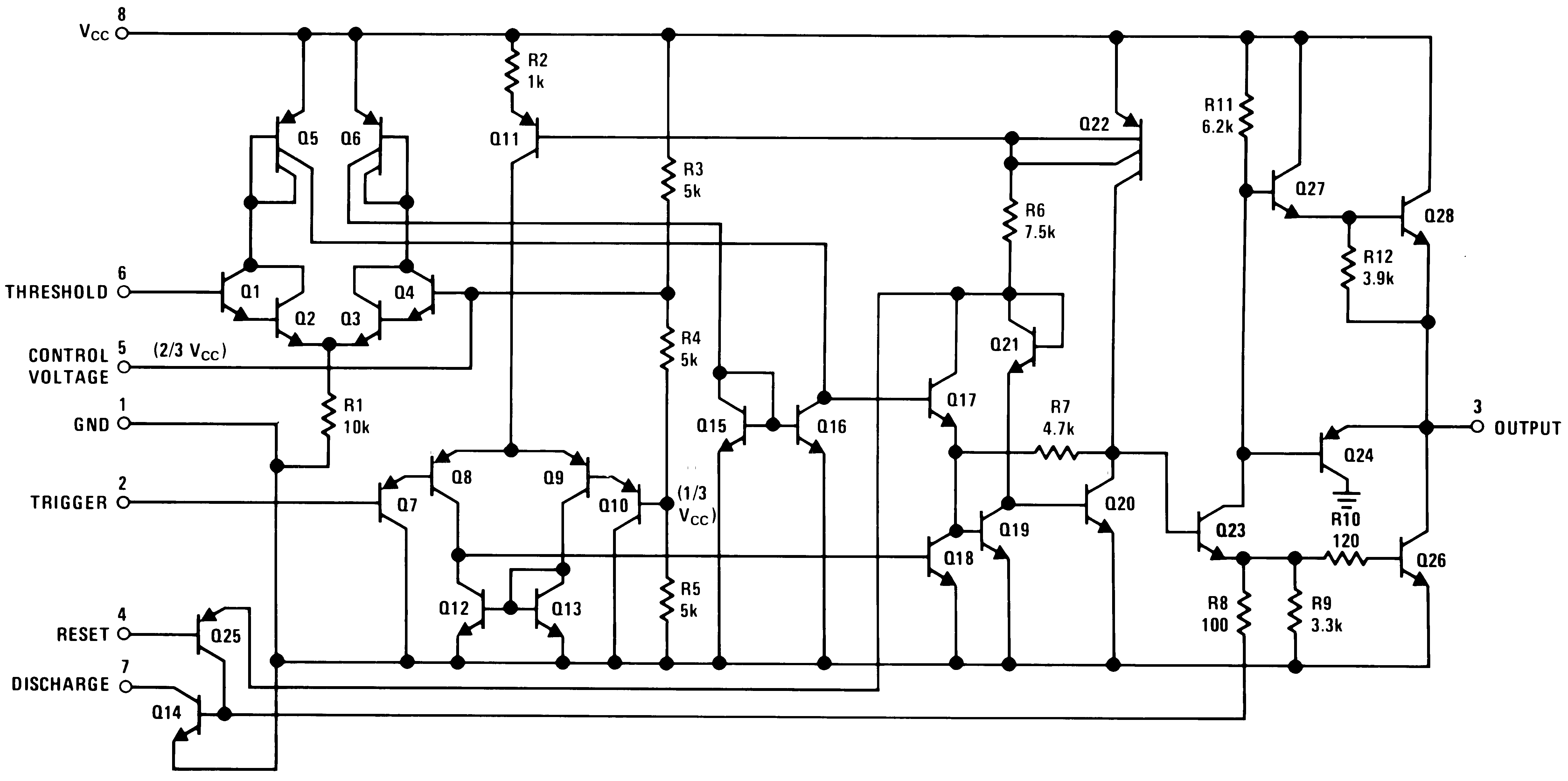
Schematic Diagram
4 Revision History
| DATE | REVISION | NOTES |
|---|---|---|
| June 2017 | * | Initial release. |
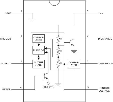
5 Pin Configuration and Functions
Pin Functions
| PIN | I/O | DESCRIPTION | |
|---|---|---|---|
| NO. | NAME | ||
| 5 | Control Voltage | I | Controls the threshold and trigger levels. It determines the pulse width of the output waveform. An external voltage applied to this pin can also be used to modulate the output waveform |
| 7 | Discharge | I | Open collector output which discharges a capacitor between intervals (in phase with output). It toggles the output from high to low when voltage reaches 2/3 of the supply voltage |
| 1 | GND | O | Ground reference voltage |
| 3 | Output | O | Output driven waveform |
| 4 | Reset | I | Negative pulse applied to this pin to disable or reset the timer. When not used for reset purposes, it should be connected to VCC to avoid false triggering |
| 6 | Threshold | I | Compares the voltage applied to the terminal with a reference voltage of 2/3 Vcc. The amplitude of voltage applied to this terminal is responsible for the set state of the flip-flop |
| 2 | Trigger | I | Responsible for transition of the flip-flop from set to reset. The output of the timer depends on the amplitude of the external trigger pulse applied to this pin. |
| 8 | V+ | I | Supply voltage with respect to GND |
6 Specifications
6.1 Absolute Maximum Ratings
over operating free-air temperature range (unless otherwise noted)(1)(2)| MIN | MAX | UNIT | |||
|---|---|---|---|---|---|
| Power Dissipation(3) | LM555CM, LM555CN(4) | 1180 | mW | ||
| LM555CMM | 613 | mW | |||
| Soldering Information | PDIP Package | Soldering (10 Seconds) | 260 | °C | |
| Small Outline Packages (SOIC and VSSOP) | Vapor Phase (60 Seconds) | 215 | °C | ||
| Infrared (15 Seconds) | 220 | °C | |||
| Storage temperature, Tstg | –65 | 150 | °C | ||
6.2 ESD Ratings
| VALUE | UNIT | |||
|---|---|---|---|---|
| V(ESD) | Electrostatic discharge | Human-body model (HBM), per ANSI/ESDA/JEDEC JS-001(1) | ±500(2) | V |
6.3 Recommended Operating Conditions
over operating free-air temperature range (unless otherwise noted)| MIN | MAX | UNIT | ||
|---|---|---|---|---|
| Supply Voltage | 18 | V | ||
| Operating free-air temperature, TA | 0 | 70 | °C | |
| Operating junction temperature, TJ | 70 | °C | ||
6.4 Thermal Information
| THERMAL METRIC(1) | LM555-MIL | UNIT | |||
|---|---|---|---|---|---|
| PDIP | SOIC | VSSOP | |||
| 8 PINS | 8 PINS | 8 PINS | |||
| RθJA | Junction-to-ambient thermal resistance | 106 | 170 | 204 | °C/W |
6.5 Electrical Characteristics
(TA = 25°C, VCC = 5 V to 15 V, unless otherwise specified)(1)(2)| PARAMETER | TEST CONDITIONS | MIN | TYP | MAX | UNIT |
|---|---|---|---|---|---|
| Supply Voltage | 4.5 | 16 | V | ||
| Supply Current | VCC = 5 V, RL = ∞ | 3 | 6 | mA | |
| VCC = 15 V, RL = ∞ (Low State) (3) |
10 | 15 | |||
| Timing Error, Monostable | |||||
| Initial Accuracy | 1 % | ||||
| Drift with Temperature | RA = 1 k to 100 kΩ, | 50 | ppm/°C | ||
| C = 0.1 μF, (4) | |||||
| Accuracy over Temperature | 1.5 % | ||||
| Drift with Supply | 0.1 % | V | |||
| Timing Error, Astable | |||||
| Initial Accuracy | 2.25 | ||||
| Drift with Temperature | RA, RB =1 k to 100 kΩ, | 150 | ppm/°C | ||
| C = 0.1 μF, (4) | |||||
| Accuracy over Temperature | 3.0% | ||||
| Drift with Supply | 0.30 % | /V | |||
| Threshold Voltage | 0.667 | x VCC | |||
| Trigger Voltage | VCC = 15 V | 5 | V | ||
| VCC = 5 V | 1.67 | V | |||
| Trigger Current | 0.5 | 0.9 | μA | ||
| Reset Voltage | 0.4 | 0.5 | 1 | V | |
| Reset Current | 0.1 | 0.4 | mA | ||
| Threshold Current | (5) | 0.1 | 0.25 | μA | |
| Control Voltage Level | VCC = 15 V | 9 | 10 | 11 | V |
| VCC = 5 V | 2.6 | 3.33 | 4 | ||
| Pin 7 Leakage Output High | 1 | 100 | nA | ||
| Pin 7 Sat (6) | |||||
| Output Low | VCC = 15 V, I7 = 15 mA | 180 | mV | ||
| Output Low | VCC = 4.5 V, I7 = 4.5 mA | 80 | 200 | mV | |
| Output Voltage Drop (Low) | VCC = 15 V | ||||
| ISINK = 10 mA | 0.1 | 0.25 | V | ||
| ISINK = 50 mA | 0.4 | 0.75 | V | ||
| ISINK = 100 mA | 2 | 2.5 | V | ||
| ISINK = 200 mA | 2.5 | V | |||
| VCC = 5 V | |||||
| ISINK = 8 mA | V | ||||
| ISINK = 5 mA | 0.25 | 0.35 | V | ||
| Output Voltage Drop (High) | ISOURCE = 200 mA, VCC = 15 V | 12.5 | V | ||
| ISOURCE = 100 mA, VCC = 15 V | 12.75 | 13.3 | V | ||
| VCC = 5 V | 2.75 | 3.3 | V | ||
| Rise Time of Output | 100 | ns | |||
| Fall Time of Output | 100 | ns |
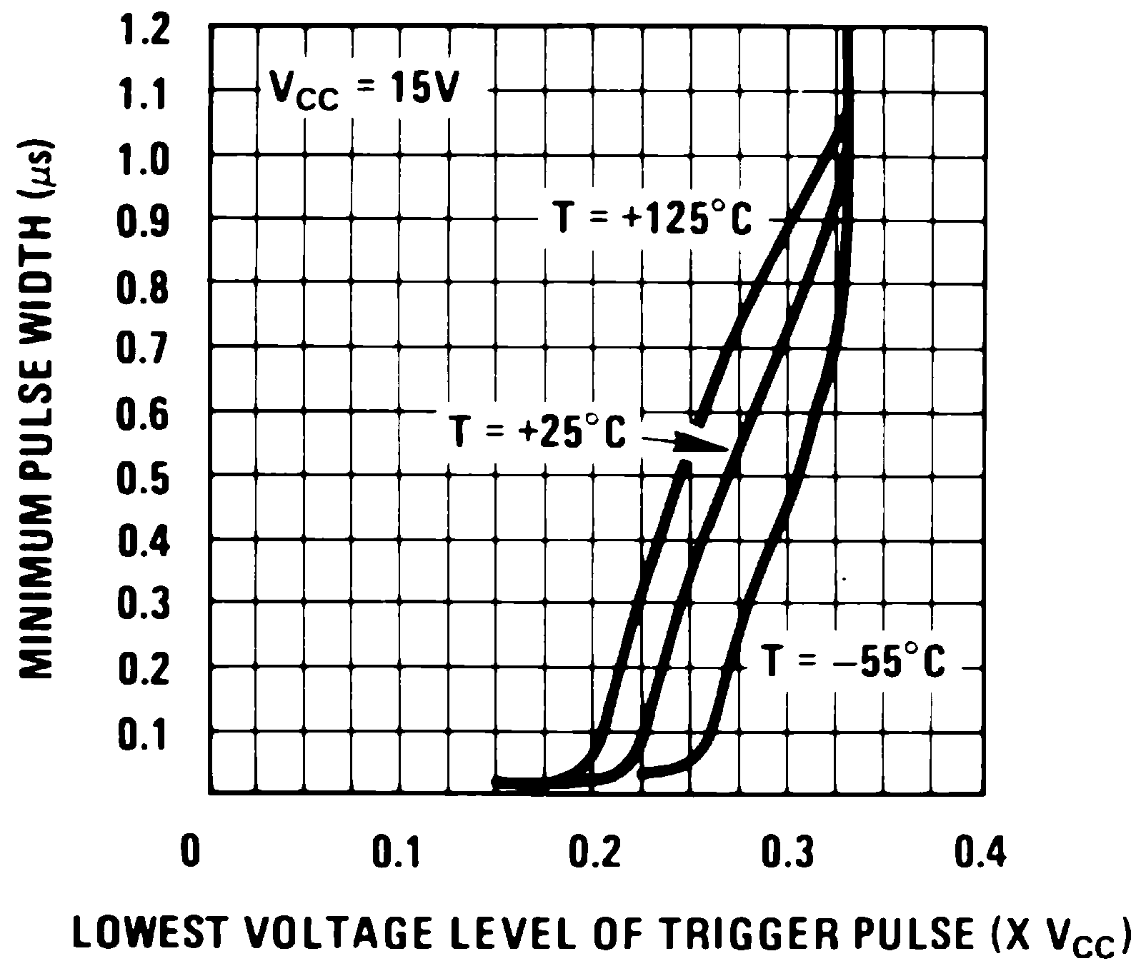
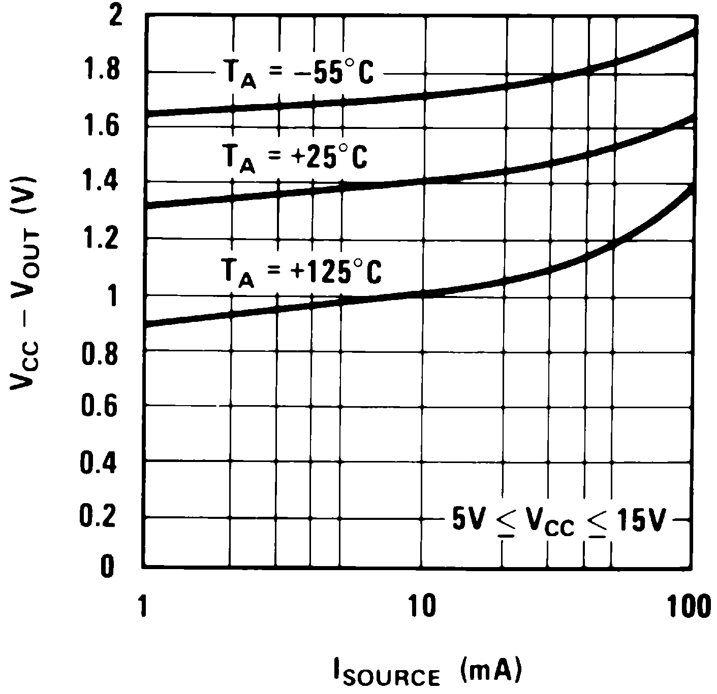
6.6 Typical Characteristics
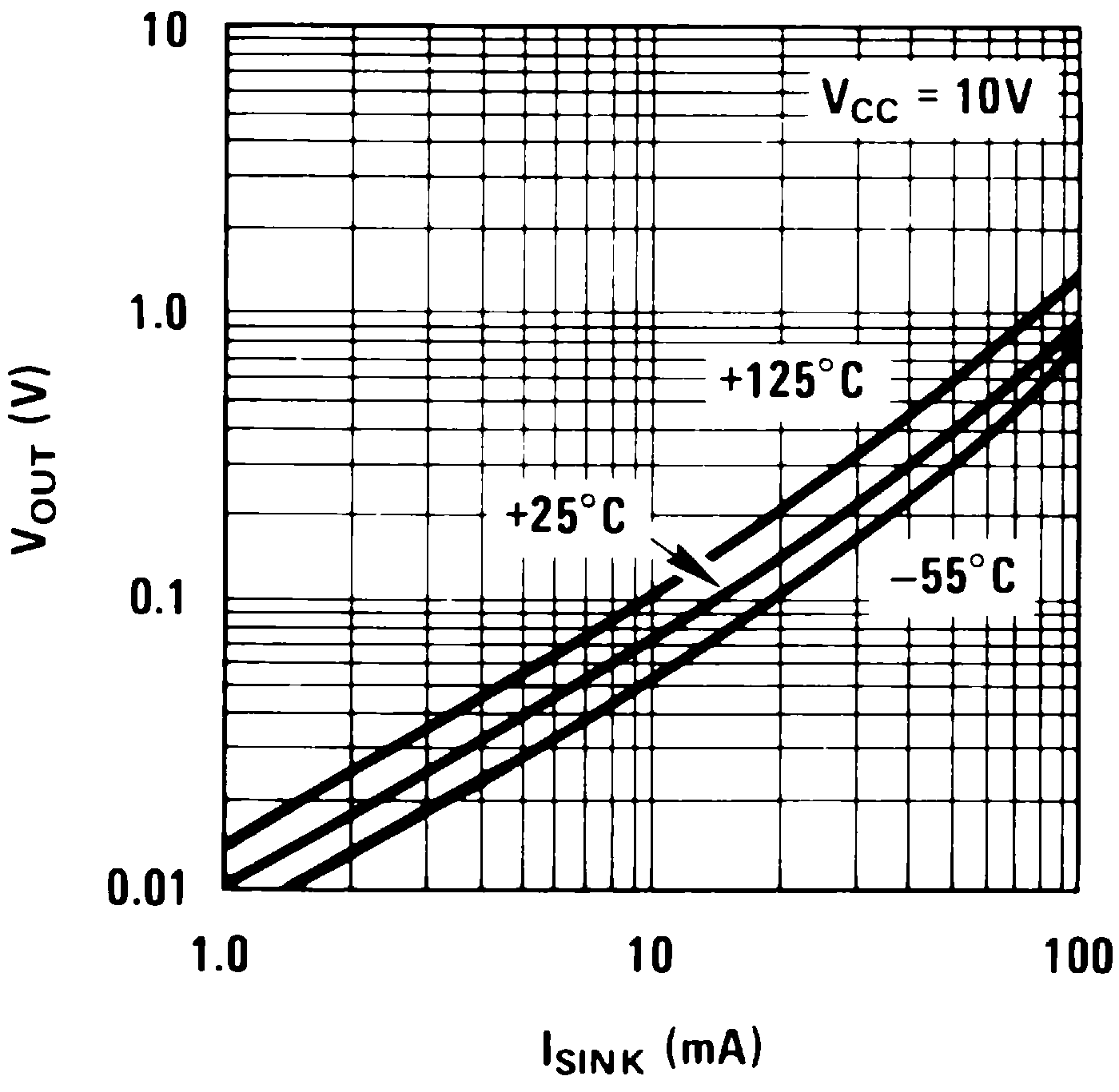
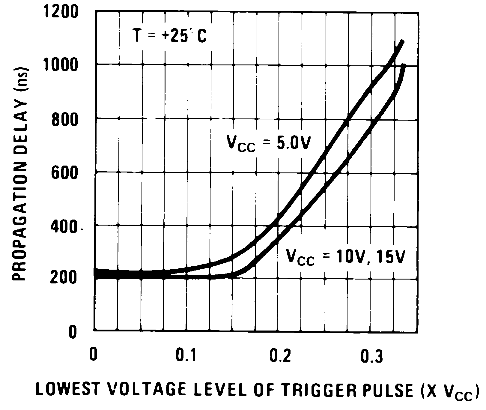
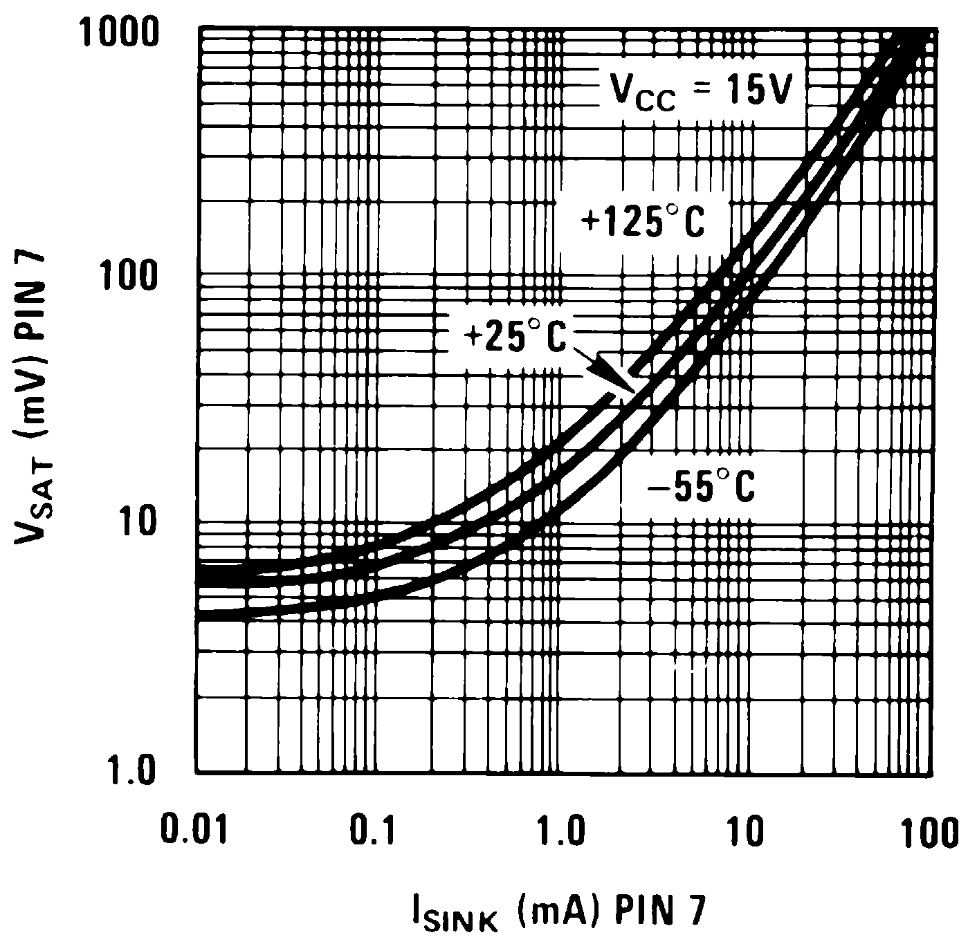
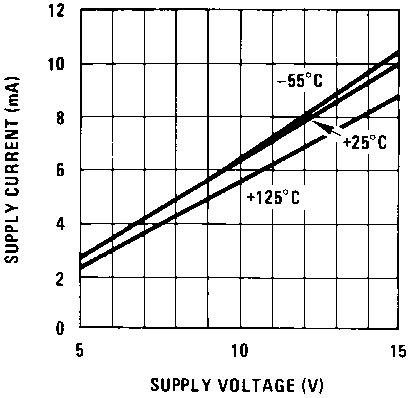
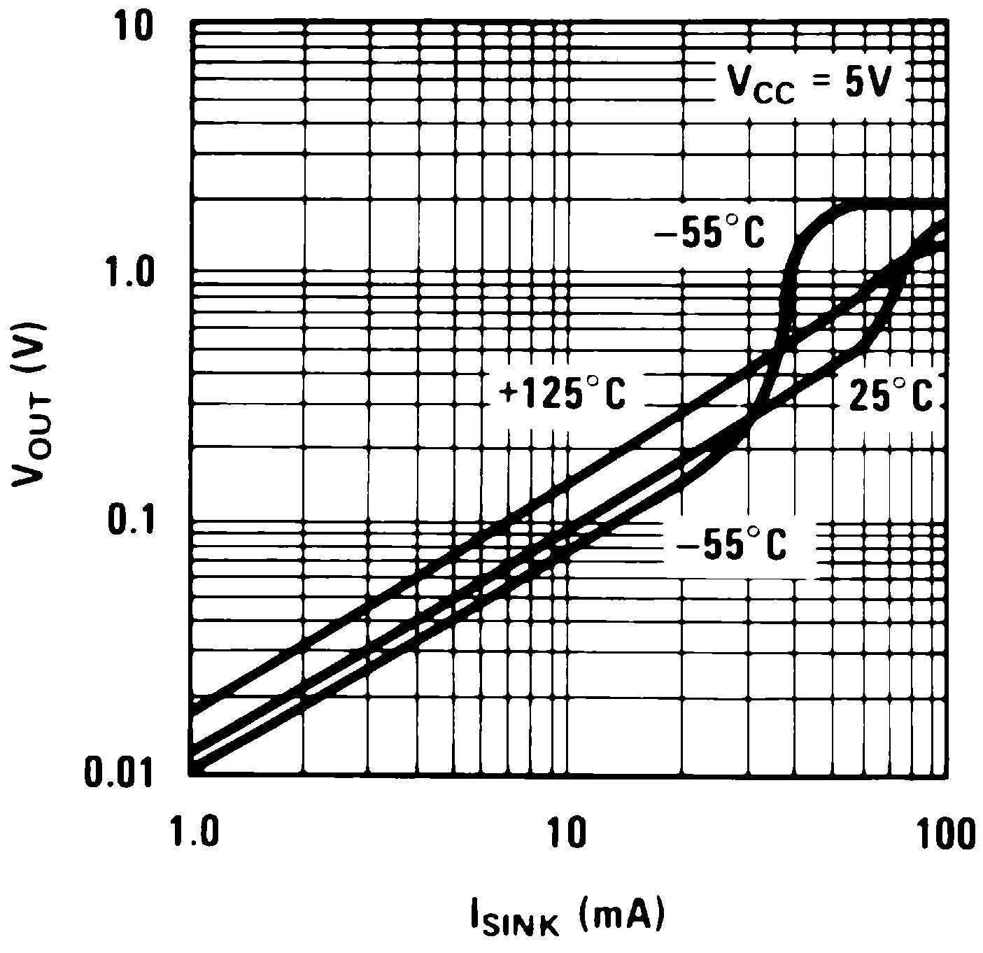
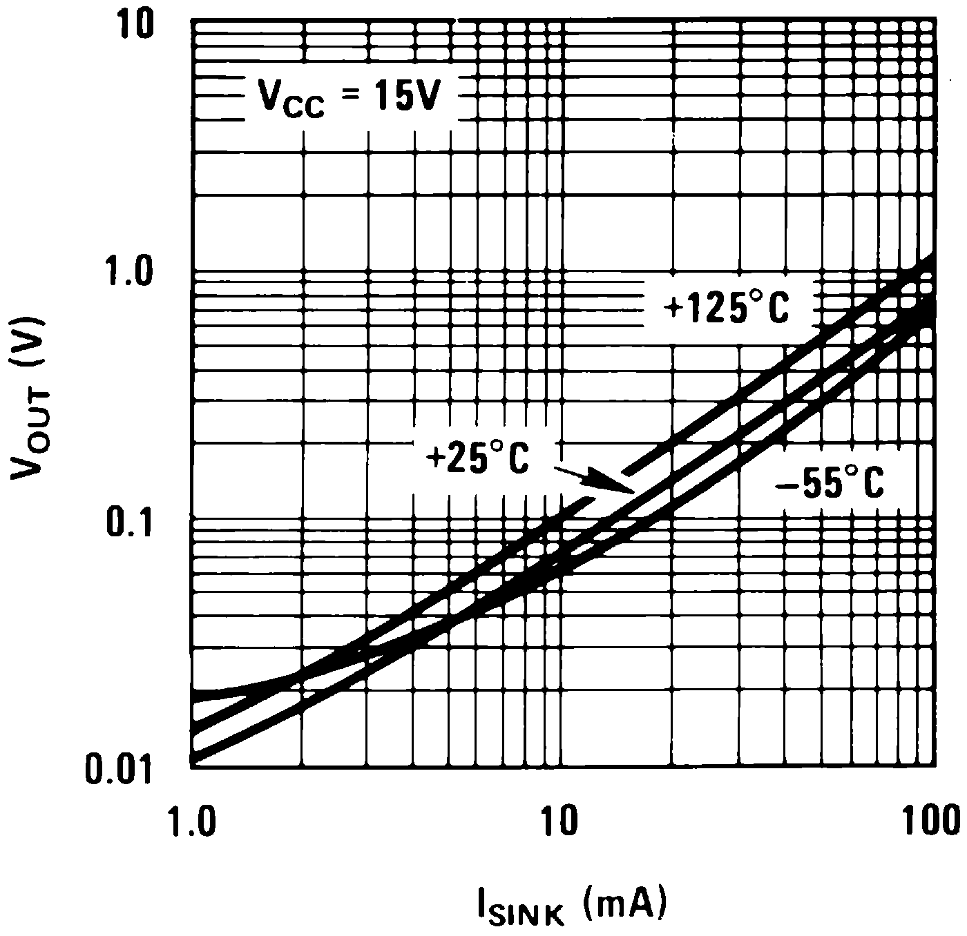
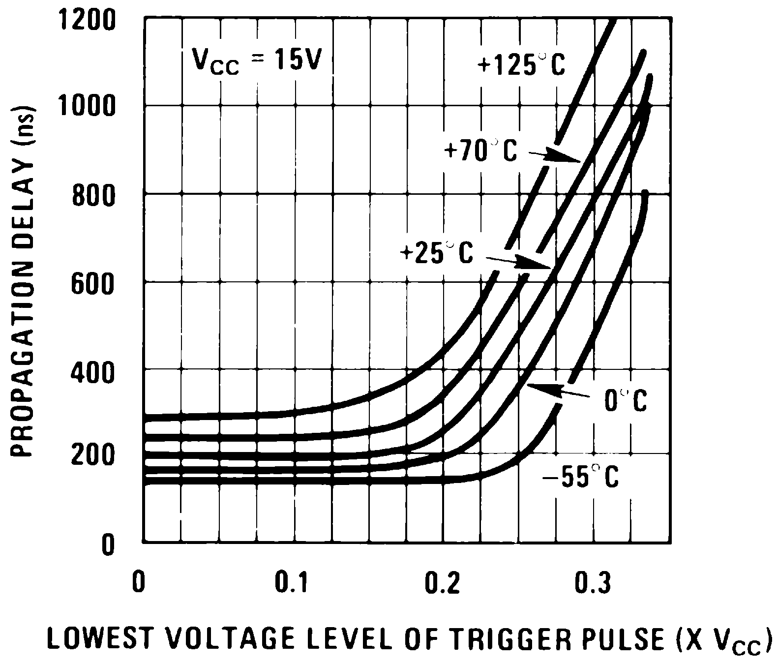
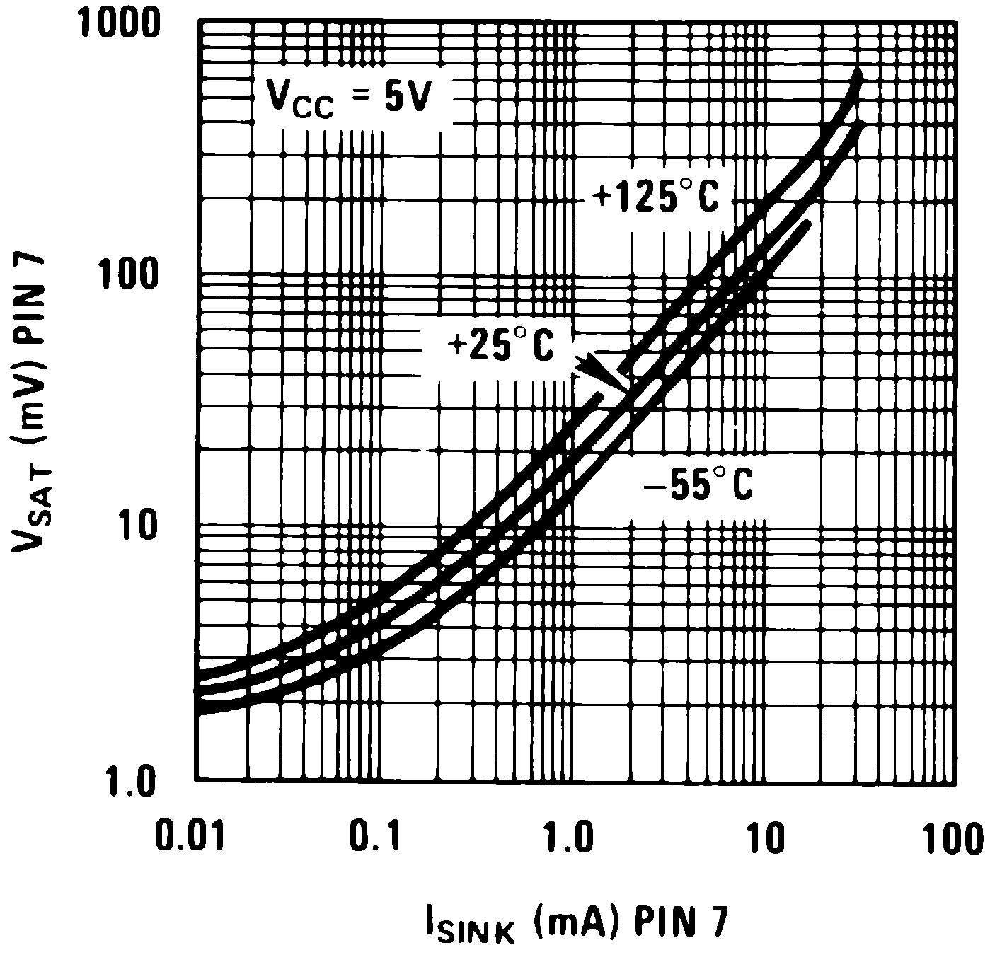
7 Detailed Description
7.1 Overview
The LM555-MIL is a highly stable device for generating accurate time delays or oscillation. Additional terminals are provided for triggering or resetting if desired. In the time delay mode of operation, the time is precisely controlled by one external resistor and capacitor. For astable operation as an oscillator, the free running frequency and duty cycle are accurately controlled with two external resistors and one capacitor. The circuit may be triggered and reset on falling waveforms, and the output circuit can source or sink up to 200 mA or driver TTL circuits. The LM555-MIL are available in 8-pin PDIP, SOIC, and VSSOP packages and is a direct replacement for SE555/NE555.
7.2 Functional Block Diagram
7.3 Feature Description
7.3.1 Direct Replacement for SE555/NE555
The LM555-MIL timer is a direct replacement for SE555 and NE555. It is pin-to-pin compatible so that no schematic or layout changes are necessary. The LM555-MIL come in an 8-pin PDIP, SOIC, and VSSOP package.
7.3.2 Timing From Microseconds Through Hours
The LM555-MIL has the ability to have timing parameters from the microseconds range to hours. The time delay of the system can be determined by the time constant of the R and C value used for either the monostable or astable configuration. A nomograph is available for easy determination of R and C values for various time delays.
7.3.3 Operates in Both Astable and Monostable Mode
The LM555-MIL can operate in both astable and monostable mode depending on the application requirements.
- Monostable mode: The LM555-MIL timer acts as a “one-shot” pulse generator. The pulse beings when the LM555-MIL timer receives a signal at the trigger input that falls below a 1/3 of the voltage supply. The width of the output pulse is determined by the time constant of an RC network. The output pulse ends when the voltage on the capacitor equals 2/3 of the supply voltage. The output pulse width can be extended or shortened depending on the application by adjusting the R and C values.
- Astable (free-running) mode: The LM555-MIL timer can operate as an oscillator and puts out a continuous stream of rectangular pulses having a specified frequency. The frequency of the pulse stream depends on the values of RA, RB, and C.
7.4 Device Functional Modes
7.4.1 Monostable Operation
In this mode of operation, the timer functions as a one-shot (Figure 11). The external capacitor is initially held discharged by a transistor inside the timer. Upon application of a negative trigger pulse of less than 1/3 VCC to pin 2, the flip-flop is set which both releases the short circuit across the capacitor and drives the output high.
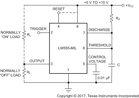 Figure 11. Monostable
The voltage across the capacitor then increases exponentially for a period of t = 1.1 RA C, at the end of which time the voltage equals 2/3 VCC. The comparator then resets the flip-flop which in turn discharges the capacitor and drives the output to its low state. Figure 12 shows the waveforms generated in this mode of operation. Since the charge and the threshold level of the comparator are both directly proportional to supply voltage, the timing interval is independent of supply.
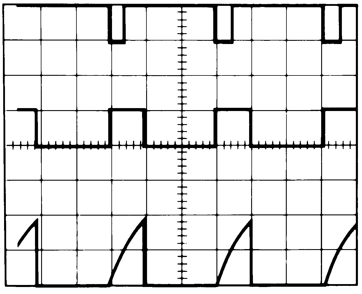
TIME = 0.1 ms/DIV. Middle Trace: Output 5V/Div.
RA = 9.1 kΩ Bottom Trace: Capacitor Voltage 2V/Div.
C = 0.01 μF
During the timing cycle when the output is high, the further application of a trigger pulse will not effect the circuit so long as the trigger input is returned high at least 10 μs before the end of the timing interval. However the circuit can be reset during this time by the application of a negative pulse to the reset terminal (pin 4). The output will then remain in the low state until a trigger pulse is again applied.
When the reset function is not in use, TI recommends connecting the Reset pin to VCC to avoid any possibility of false triggering.
Figure 13 is a nomograph for easy determination of R, C values for various time delays.
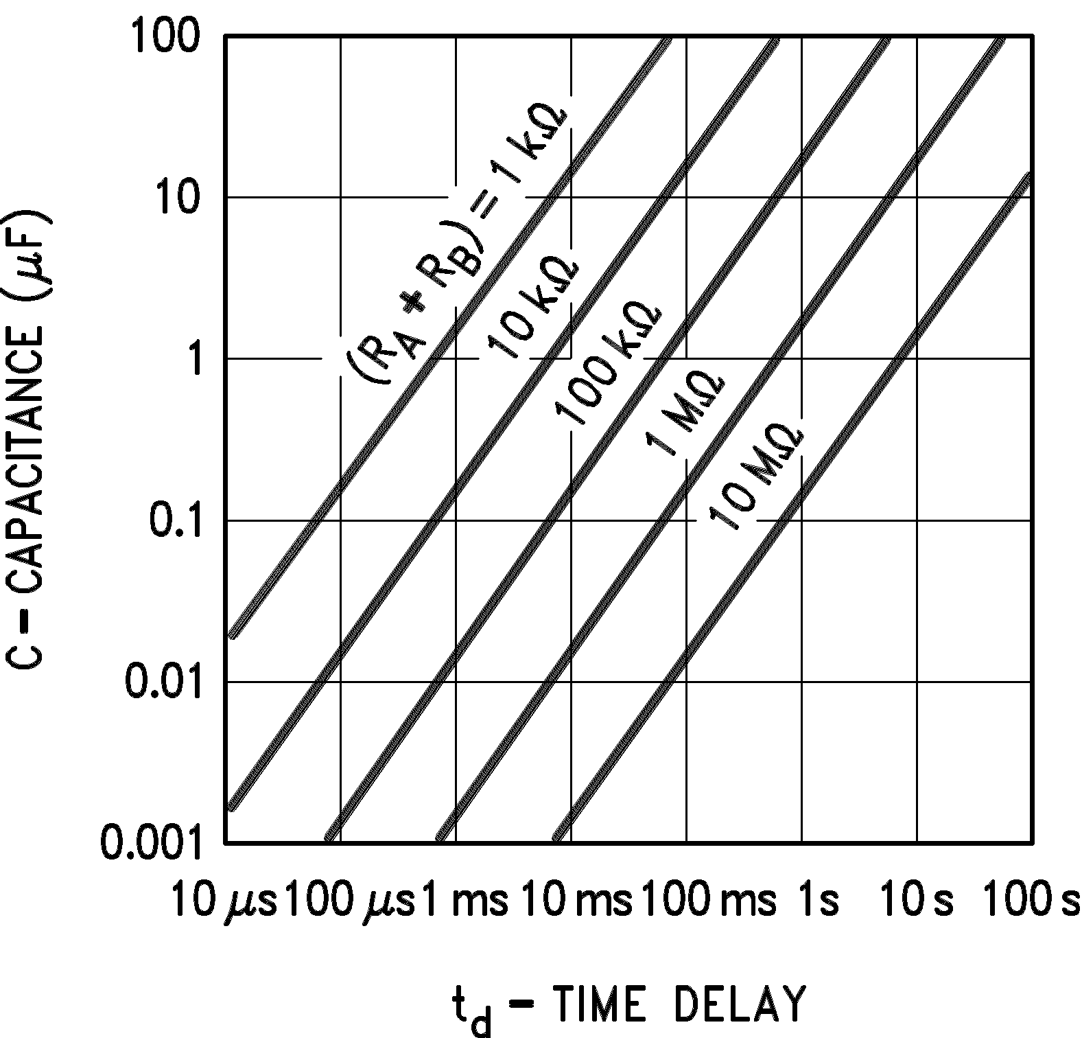 Figure 13. Time Delay
7.4.2 Astable Operation
If the circuit is connected as shown in Figure 14 (pins 2 and 6 connected) it will trigger itself and free run as a multivibrator. The external capacitor charges through RA + RB and discharges through RB. Thus the duty cycle may be precisely set by the ratio of these two resistors.
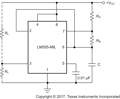 Figure 14. Astable
In this mode of operation, the capacitor charges and discharges between 1/3 VCC and 2/3 VCC. As in the triggered mode, the charge and discharge times, and therefore the frequency are independent of the supply voltage.
Figure 15 shows the waveforms generated in this mode of operation.
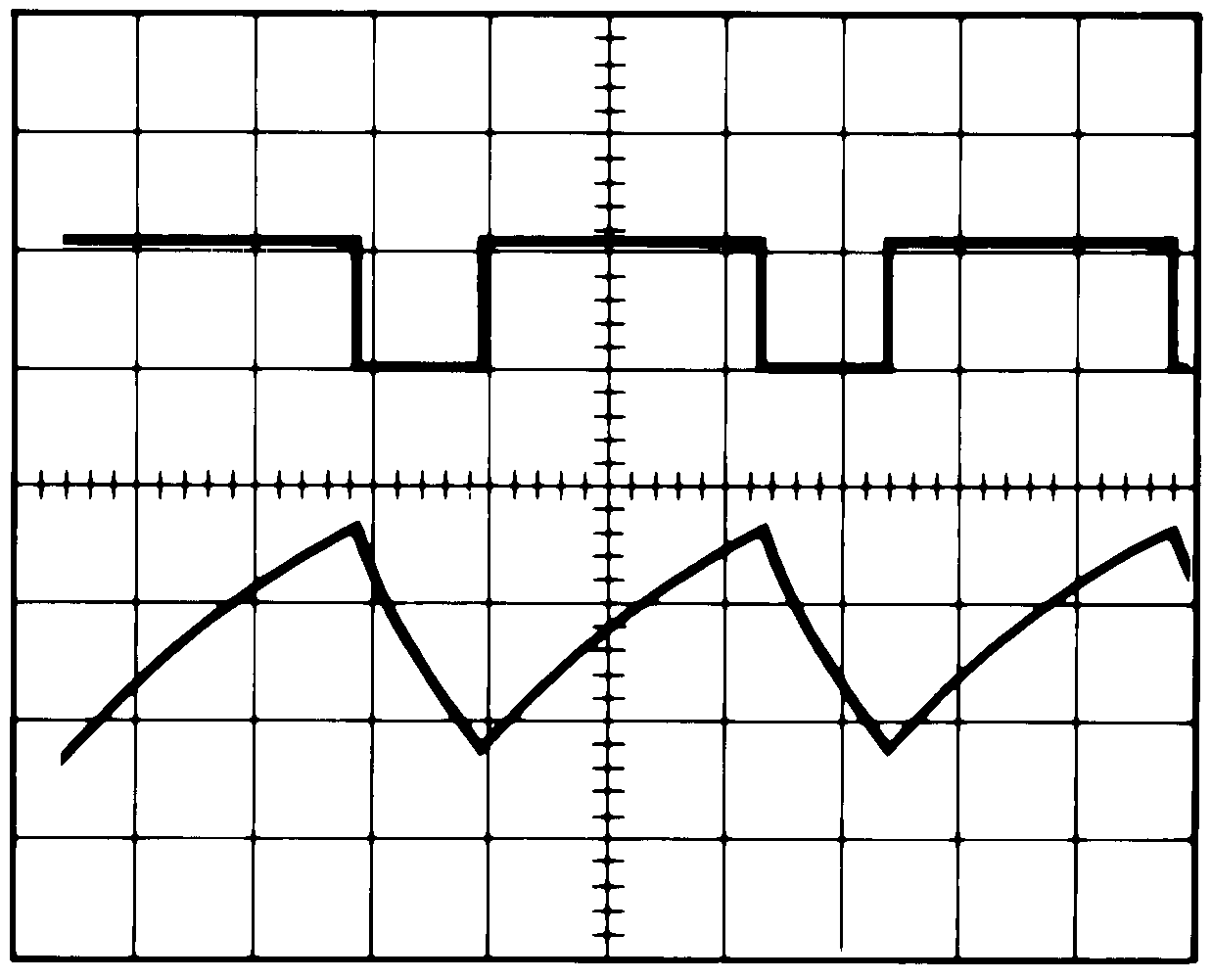
TIME = 20μs/DIV. Bottom Trace: Capacitor Voltage 1V/Div.
RA = 3.9 kΩ
RB = 3 kΩ
C = 0.01 μF
The charge time (output high) is given by:
And the discharge time (output low) by:
Thus the total period is:
The frequency of oscillation is:

Figure 16 may be used for quick determination of these RC values.
The duty cycle is:
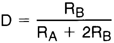
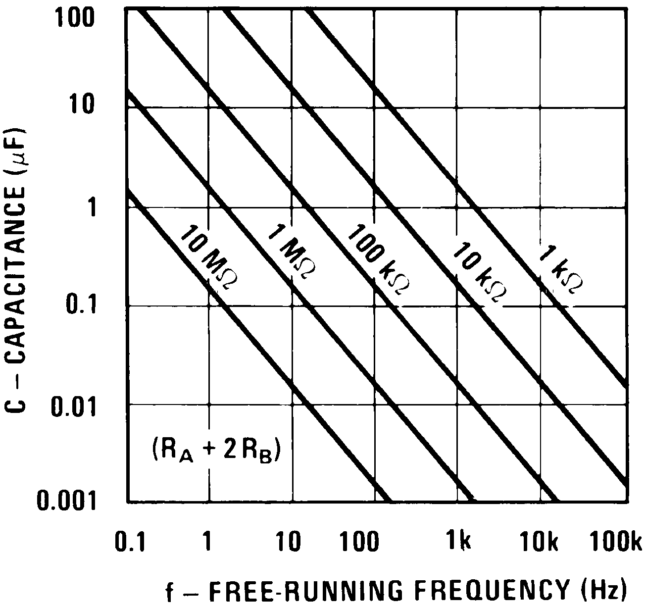 Figure 16. Free Running Frequency
8 Application and Implementation
NOTE
Information in the following applications sections is not part of the TI component specification, and TI does not warrant its accuracy or completeness. TI’s customers are responsible for determining suitability of components for their purposes. Customers should validate and test their design implementation to confirm system functionality.
8.1 Application Information
The LM555-MIL timer can be used a various configurations, but the most commonly used configuration is in monostable mode. A typical application for the LM555-MIL timer in monostable mode is to turn on an LED for a specific time duration. A pushbutton is used as the trigger to output a high pulse when trigger pin is pulsed low. This simple application can be modified to fit any application requirement.
8.2 Typical Application
Figure 17 shows the schematic of the LM555-MIL that flashes an LED in monostable mode.
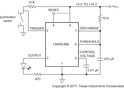 Figure 17. Schematic of Monostable Mode to Flash an LED
8.2.1 Design Requirements
The main design requirement for this application requires calculating the duration of time for which the output stays high. The duration of time is dependent on the R and C values (as shown in Figure 17) and can be calculated by:
8.2.2 Detailed Design Procedure
To allow the LED to flash on for a noticeable amount of time, a 5 second time delay was chosen for this application. By using Equation 6, RC equals 4.545. If R is selected as 100 kΩ, C = 45.4 µF. The values of R = 100 kΩ and C = 47 µF was selected based on standard values of resistors and capacitors. A momentary push button switch connected to ground is connected to the trigger input with a 10-K current limiting resistor pullup to the supply voltage. When the push button is pressed, the trigger pin goes to GND. An LED is connected to the output pin with a current limiting resistor in series from the output of the LM555-MIL to GND. The reset pin is not used and was connected to the supply voltage.
8.2.2.1 Frequency Divider
The monostable circuit of Figure 11 can be used as a frequency divider by adjusting the length of the timing cycle. Figure 18 shows the waveforms generated in a divide by three circuit.
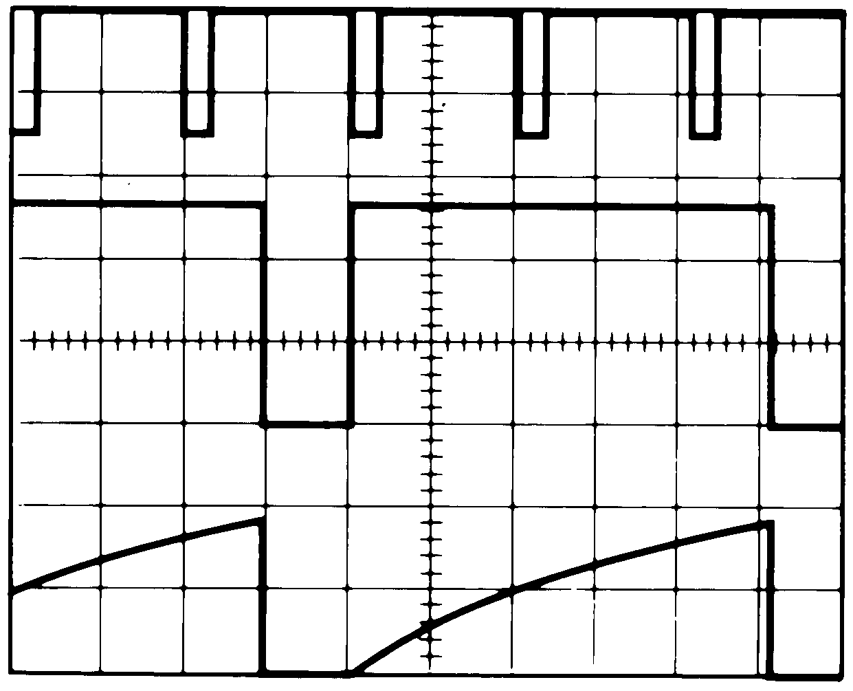
TIME = 20 μs/DIV. Middle Trace: Output 2V/Div.
RA = 9.1 kΩ Bottom Trace: Capa citor 2V/Div.
C = 0.01 μF
8.2.2.2 Additional Information
Lower comparator storage time can be as long as 10 μs when pin 2 is driven fully to ground for triggering. This limits the monostable pulse width to 10 μs minimum.
Delay time reset to output is 0.47 μs typical. Minimum reset pulse width must be 0.3 μs, typical.
Pin 7 current switches within 30 ns of the output (pin 3) voltage.
8.2.3 Application Curves
The data shown below was collected with the circuit used in the typical applications section. The LM555-MIL was configured in the monostable mode with a time delay of 5.17 s. The waveforms correspond to:
- Top Waveform (Yellow) – Capacitor voltage
- Middle Waveform (Green) – Trigger
- Bottom Waveform (Purple) – Output
As the trigger pin pulses low, the capacitor voltage starts charging and the output goes high. The output goes low as soon as the capacitor voltage reaches 2/3 of the supply voltage, which is the time delay set by the R and C value. For this example, the time delay is 5.17 s.
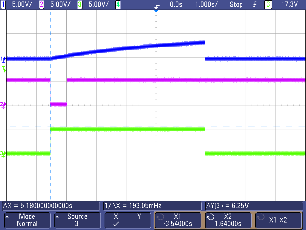 Figure 19. Trigger, Capacitor Voltage, and Output Waveforms in Monostable Mode