SNOSDB7 December 2020 LM74500-Q1
PRODUCTION DATA
- 1 Features
- 2 Applications
- 3 Description
- 4 Revision History
- 5 Pin Configuration and Functions
- 6 Specifications
- 7 Typical Characteristics
- 8 Detailed Description
-
9 Application and Implementation
- 9.1 Reverse Battery Protection for Automotive Body Control Module Applications
- 9.2 Reverse Polarity Protection
- 9.3 Application Information
- 10Power Supply Recommendations
- 11Layout
- 12Device and Documentation Support
- 13Mechanical, Packaging, and Orderable Information
Package Options
Mechanical Data (Package|Pins)
- DDF|8
Thermal pad, mechanical data (Package|Pins)
Orderable Information
9.1 Reverse Battery Protection for Automotive Body Control Module Applications
Reverse-battery protection activates when battery terminals are incorrectly connected during jump start, vehicle maintenance or service because a connection error can damage the components in ECUs if they are not rated to handle reverse polarity. An N-channel MOSFET (N-FET) based reverse polarity protection solutions are becoming obivious choice over discrete reverse-battery protection solutions like Schottky diodes and P-channel field-effect transistors (P-FETs) due to their better power and thermal efficiency and the comparitively smaller space they consume on a printed circuit board. Based on the application needs, reverse polarity protection solutions can be divided into two main categories
- Applications which need both input reverse polarity protection and reverse current blocking
- Applications which need only input reverse polarity protection and does not need reverse current blocking
Figure 9-1 provides an overview of these two reverse polarity protection solution categories. Typically for applications where output loads are DC/DC converters, voltage regulator followed by MCU/processors (Logic paths), input reverse polarity protection and reverse current blocking feature is required. For reverse polarity protection solution of the logic path ideal diode controllers such as LM74700-Q1 is a suitable device.
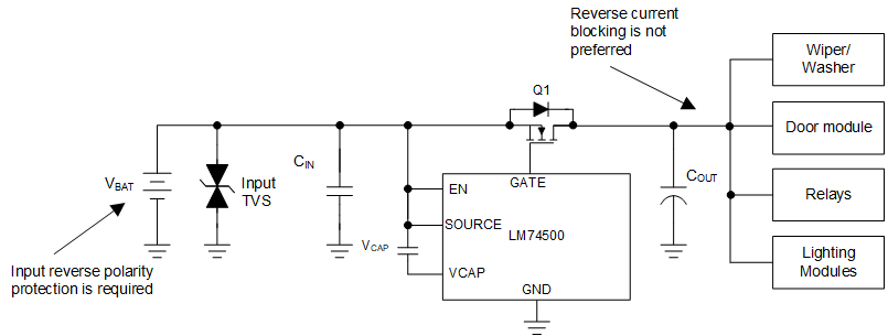
For the applications such as Body Control Module (BCM) load driving paths, input reverse polarity protection is required but reverse current blocking is not a must have feature. For reverse polarity protection solution of the BCM load driving paths, reverse polarity potection controllers such as LM74500-Q1 is a suitable device.
 Figure 9-1 Typical Block Diagram for Automotive BCM Reverse Battery Protection Solution.
 For certain applications such as body control module load driving paths where output loads are inductive in nature such as wiper motor, door control module, it is required that reverse polarity protection device should provide protection against incorrect input polarity. However, it should not block reverse current from loads back to the battery. This is mainly required to avoid voltage overshoot which is caused when inductive loads are turned off. If reverse polarity protection device blocks the reverse current then there could be voltage overshoot caused due to inductive kick back or motor regenrative action and can damage parallel loads connected on the output of reverse polarity protection device. For certain specific loads such as wiper motor, a voltage overshoot is seen due to transformer effect when wiper motor speed is changed from fast speed to slow speed. LM74500-Q1 is designed to provide protection against input reverse polarity for such applications where reverse current blocking is not reuiqred. Figure 9-2 shows typical application circuit of reverse polarity protection of body control module load driving paths.
 Figure 9-2 Typical Block Diagram of
Reverse Battery Protection for Body Control Module Load Driving Path.