SNOS738I April 1995 – January 2017 LM9061 , LM9061-Q1
PRODUCTION DATA.
- 1 Features
- 2 Applications
- 3 Description
- 4 Revision History
- 5 Pin Configuration and Functions
- 6 Specifications
- 7 Detailed Description
- 8 Application and Implementation
- 9 Power Supply Recommendations
- 10Layout
- 11Device and Documentation Support
- 12Mechanical, Packaging, and Orderable Information
Package Options
Mechanical Data (Package|Pins)
- D|8
Thermal pad, mechanical data (Package|Pins)
Orderable Information
10 Layout
10.1 Layout Guidelines
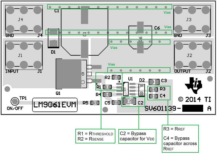
- The bypass capacitor for VCC must be placed as close as possible to the VCC pin.
- The resistor RREF must be placed as close as possible to the IREF and Ground pins with minimal trace length to keep the IREF current as accurate as possible. The LM9061 is optimized for use with a 15.4 kΩ ±1% resistor for RREF.
- In applications where the VCC supply is subject to high levels of transient noise, a bypass capacitor across RREF is recommended. This bypass capacitor must be no larger than 0.1 μF and must be placed as close as possible to the IREF pin.
- The RTHRESHOLD and RSENSE resistors must be placed as close as possible to the MOSFET drain and source pins respectively. This allows accurate monitoring of the VDS voltage across the MOSFET.
- An array of vias can be placed along the high current path to the output load. These vias can help conduct heat to any inner plane areas or to a bottom-side copper plane.
10.2 Layout Examples
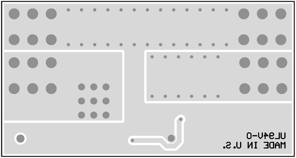
Figure 26 and Figure 27 are layout examples for the LM9061 and LM9061-Q1. These examples are taken from the LM9061EVM. For information on the operation and schematic of the EVM, see LM9061 High-Side Protection Controller EVM (SNOU132).
 Figure 26. LM9061EVM Layout Example (Top)
 Figure 27. LM9061EVM Layout Example (Bottom)