SNWS022D January 2010 – June 2015 LMH2110
PRODUCTION DATA.
- 1 Features
- 2 Applications
- 3 Description
- 4 Revision History
- 5 Pin Configuration and Functions
- 6 Specifications
- 7 Detailed Description
-
8 Application and Implementation
- 8.1 Application Information
- 8.2 Typical Applications
- 9 Power Supply Recommendations
- 10Layout
- 11Device and Documentation Support
- 12Mechanical, Packaging, and Orderable Information
Package Options
Mechanical Data (Package|Pins)
- YFQ|6
Thermal pad, mechanical data (Package|Pins)
Orderable Information
10 Layout
10.1 Layout Guidelines
As with any other RF device, pay close careful attention to the board layout. If the board layout is not properly designed, performance might be less then can be expected for the application.
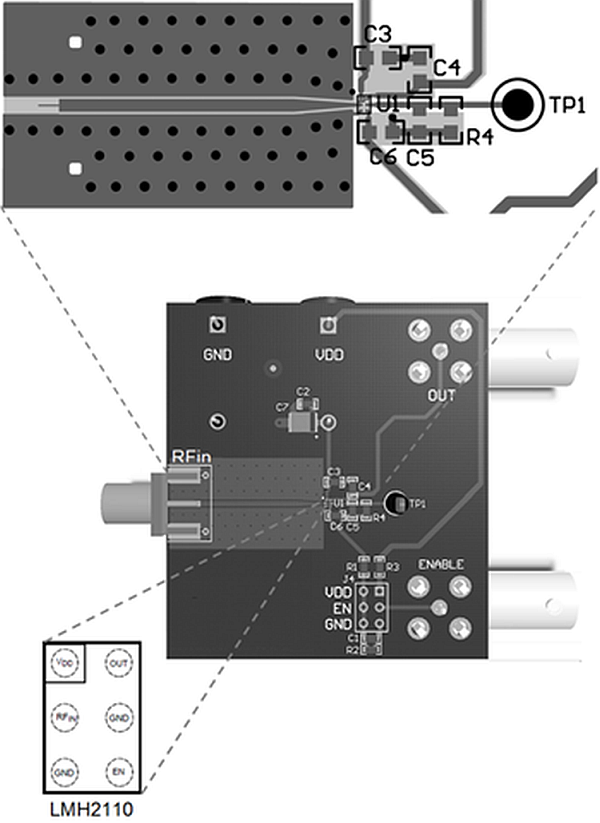
The LMH2110 is designed to be used in RF applications, having a characteristic impedance of 50 Ω. To achieve this impedance, the input of the LMH2110 needs to be connected via a 50-Ω transmission line. Transmission lines can be created on PCBs using microstrip or (grounded) coplanar waveguide (GCPW) configurations.
In order to minimize injection of RF interference into the LMH2110 through the supply lines, the PCB traces for VDD and GND must be minimized for RF signals. This can be done by placing a small decoupling capacitor between the VDD and GND. It must be placed as close as possible to the VDD and GND pins of the LMH2110.
10.2 Layout Example
 Figure 56. LMH2110 Layout