SNOSAL8D April 2006 – September 2021 LMH6321
PRODUCTION DATA
- 1Features
- 2Applications
- 3Description
- 4Revision History
- 5Specifications
- 6Application Hints
- 7Device and Documentation Support
- 8Mechanical, Packaging, and Orderable Information
Package Options
Refer to the PDF data sheet for device specific package drawings
Mechanical Data (Package|Pins)
- KTW|7
- DDA|8
Thermal pad, mechanical data (Package|Pins)
Orderable Information
6.2 Supply Bypassing
The method of supply bypassing is not critical for frequency stability of the buffer, and, for light loads, capacitor values in the neighborhood of 1 nF to 10 nF are adequate. However, under fast slewing and large loads, large transient currents are demanded of the power supplies, and when combined with any significant wiring inductance, these currents can produce voltage transients. For example, the LMH6321 can slew typically at 1000 V/μs. Therefore, under a 50 Ω load condition the load can demand current at a rate, di/dt, of 20 A/μs. This current flowing in an inductance of 50 nH (approximately 1.5” of 22 gauge wire) will produce a 1 V transient. Thus, it is recommended that solid tantalum capacitors of 5 μF to 10 μF, in parallel with a ceramic 0.1 μF capacitor be added as close as possible to the device supply pins.
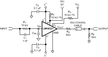
 Figure 6-2 50 Ω Coaxial Cable Driver with
Dual Supplies
Figure 6-2 50 Ω Coaxial Cable Driver with
Dual SuppliesFor values of capacitors in the 10 μF to 100 μF range, ceramics are usually larger and more costly than tantalums but give superior AC performance for bypassing high frequency noise because of their very low ESR (typically less than 10 MΩ) and low ESL.