SNOSB21E May 2008 – July 2024 LMH6518
PRODUCTION DATA
- 1
- 1 Features
- 2 Applications
- 3 Description
- 4 Pin Configuration and Functions
- 5 Specifications
- 6 Detailed Description
- 7 Application and Implementation
- 8 Device and Documentation Support
- 9 Revision History
- 10Mechanical, Packaging, and Orderable Information
Package Options
Refer to the PDF data sheet for device specific package drawings
Mechanical Data (Package|Pins)
- RGH|16
Thermal pad, mechanical data (Package|Pins)
- RGH|16
Orderable Information
7.2.2.2.1 Attenuator Design
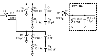
Figure 7-12 shows a front-end attenuator designed to work with Figure 7-11.
 Figure 7-12 Front-End Attenuator for JFET LNA
Implementation
Figure 7-12 Front-End Attenuator for JFET LNA
ImplementationR_LNA and C_LNA are the input impedance components of the JFET LNA. The 10:1 and 100:1 attenuators bottom resistors (R2 and R4) are adjusted higher to compensate for the LNA 1-MΩ input impedance, compared to the case where a high-input-impedance LNA is used. The two switches used on the input and output of the attenuator block are low-capacitance, high-isolation switches to reduce any speed or crosstalk impact. Capacitors C1 to C4 provide the proper frequency response (and step response) by creating zeros that flatten the response for wide-band operation. For the 10:1 attenuator, R1C1 = R2C2. The same applies to the 100:1 attenuator. The shunt capacitors, C1 to C4, have a important other benefit in that these capacitors roll off the resistor thermal noise at a low frequency (low-pass response, −3‑dB down at approximately 20‑kHz), thereby eliminating any significant noise contribution from the attenuation resistors. Otherwise, the channel noise is dominated by the attenuator resistor thermal noise. Adjust trimmer capacitors C5 and C6 to match the input capacitance regardless of attenuator used.