-
LMH6629 Ultra-Low Noise, High-Speed Operational Amplifier with Shutdown
- 1 Features
- 2 Applications
- 3 Description
- 4 Revision History
- 5 Pin Configuration and Functions
- 6 Specifications
-
7 Detailed Description
- 7.1 Overview
- 7.2 Functional Block Diagram
- 7.3
Feature Description
- 7.3.1 WSON-8 Control Pins and SOT-23-5 Comparison
- 7.3.2 Compensation
- 7.3.3 Cancellation of Offset Errors Due to Input Bias Currents
- 7.3.4 Total Input Noise vs. Source Resistance
- 7.3.5 Noise Figure
- 7.3.6 Single-Supply Operation
- 7.3.7 Low-Noise Transimpedance Amplifier
- 7.3.8 Low-Noise Integrator
- 7.3.9 High-Gain Sallen-Key Active Filters
- 7.4 Device Functional Modes
- 8 Application and Implementation
- 9 Power Supply Recommendations
- 10Layout
- 11Device and Documentation Support
- 12Mechanical, Packaging, and Orderable Information
- IMPORTANT NOTICE
Package Options
Mechanical Data (Package|Pins)
Thermal pad, mechanical data (Package|Pins)
Orderable Information
LMH6629 Ultra-Low Noise, High-Speed Operational Amplifier with Shutdown
1 Features
- Specified for VS = 5 V, RL = 100 Ω, AV = 10V/V WSON-8 Package, unless Specified. –3dB Bandwidth 900 MHz
- Input Voltage Noise 0.69 nV/√Hz
- Input Offset Voltage Max. Over Temperature ±0.8 mV
- Slew Rate 1600 V/ μs
- HD2 @ f = 1 MHz, 2VPP −90 dBc
- HD3 @ f = 1 MHz, 2VPP −94 dBc
- Supply Voltage Range 2.7 V to 5.5 V
- Typical Supply Current 15.5 mA
- Selectable Min. Gain ≥4 or ≥10 V/V
- Enable Time: 75 ns
- Output Current ±250 mA
- WSON-8 and SOT-23-5 Packages
2 Applications
- Instrumentation Amplifiers
- Ultrasound Pre-amps
- Wide-band Active Filters
- Opto-Electronics
- Medical Imaging Systems
- Base-Station Amplifiers
- Low-Noise Single Ended to Differential Conversion
- Trans-Impedance Amplifier
3 Description
The LMH6629 is a high-speed, ultra-low noise amplifier designed for applications requiring wide bandwidth with high gain and low noise such as in communication, test and measurement, optical and ultrasound systems.
The LMH6629 operates on 2.7-V to 5.5-V supply with an input common mode range that extends below ground and outputs that swing to within 0.8 V of the rails for ease of use in single supply applications. Heavy loads up to ±250 mA can be driven by high-frequency large signals with the LMH6629's –3dB bandwidth of 900 MHz and 1600 V/µs slew rate. The LMH6629 (WSON-8 package only) has user-selectable internal compensation for minimum gains of 4 or 10 controlled by pulling the COMP pin low or high, thereby avoiding the need for external compensation capacitors required in competitive devices. Compensation for the SOT-23-5 package is internally set for a minimum stable gain of 10 V/V. The WSON-8 package also provides the power-down enable/disable feature.
The low-input noise (0.69 nV/√Hz and 2.6 pA/√Hz), low distortion (HD2/HD3 = −90 dBc/−94 dBc) and ultra-low DC errors (800 µV VOS maximum over temperature, ±0.45 µV/°C drift) allow precision operation in both ac- and dc-coupled applications.
The LMH6629 is fabricated in Texas Instruments' proprietary SiGe process and is available in a 3 mm × 3 mm 8-pin WSON package as well as the SOT-23-5 package.
Device Information(1)
| PART NUMBER | PACKAGE | BODY SIZE (NOM) |
|---|---|---|
| LMH6629 | SOT-23 (5) | 2.90 mm × 1.60 mm |
| WSON (8) | 3.00 mm × 3.00 mm |
- For all available packages, see the orderable addendum at the end of the datasheet.
Transimpedance Amplifier

4 Revision History
Changes from H Revision (October 2014) to I Revision
- Updated ESD Ratings table. Go
- Revised paragraph beginning with "The optimum value of "CF in the Low-Noise Transimpedance Amplifier sectionGo
- Updated Related Documentation sectionGo
Changes from G Revision (March 2013) to H Revision
- Added, updated, or renamed the following sections: Device Information Table, Pin Configuration and Functions, Application and Implementation; Power Supply Recommendations; Layout; Device and Documentation Support; Mechanical, Packaging, and Ordering InformationGo
Changes from F Revision (March 2013) to G Revision
- Changed layout of National Data Sheet to TI formatGo
5 Pin Configuration and Functions
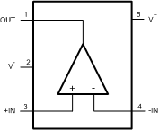

Pin Functions
| NAME | NUMBER | I/O | DESCRIPTION | |
|---|---|---|---|---|
| DBV | NGQ08A | |||
| COMP | 6 | I | Compensation | |
| FB | 2 | I/O | Feedback | |
| -IN | 4 | 3 | I | Inverting input |
| +IN | 3 | 4 | I | Non-inverting input |
| OUT | 1 | 7 | O | Output |
| PD | 1 | I | Power Down | |
| V- | 2 | 5 | I | Negative supply |
| V+ | 5 | 8 | I | Positive supply |
6 Specifications
6.1 Absolute Maximum Ratings
over operating free-air temperature range (unless otherwise noted) (1)(2)(3)| MIN | MAX | UNIT | ||
|---|---|---|---|---|
| Positive Supply Voltage | −0.5 | 6.0 | V | |
| Differential Input Voltage | 3 | V | ||
| Input current | ±10 | mA | ||
| Analog Input Voltage | −0.5 to VS | V | ||
| Digital Input Voltage | −0.5 to VS | V | ||
| Junction Temperature | +150 | °C | ||
| Storage Temperature (Tstg) | −65 | +150 | °C | |
6.2 ESD Ratings
| VALUE | UNIT | |||
|---|---|---|---|---|
| V(ESD) | Electrostatic discharge | Human-body model (HBM), per ANSI/ESDA/JEDEC JS-001(1) | ±2000 | V |
| Machine model | ±200 | |||
| Charged-device model (CDM), per JEDEC specification JESD22-C101(2) | ±750 | |||
6.3 Recommended Operating Conditions
over operating free-air temperature range (unless otherwise noted) (1)| MIN | NOM | MAX | UNIT | ||
|---|---|---|---|---|---|
| Supply Voltage (V+ - V−) | 2.7 | 5.5 | V | ||
| Operating Temperature Range | −40 | +125 | °C | ||
6.4 Thermal Information
| THERMAL METRIC(1) | DBV | NGQ08A | UNIT | |
|---|---|---|---|---|
| 5 PINS | 8 PINS | |||
| RθJA | Junction-to-ambient thermal resistance | 179 | 71 | °C/W |
6.5 Electrical Characteristics 5V
The following specifications apply for single supply with VS = 5 V, RL = 100 Ω terminated to 2.5 V, gain = 10V/V, VO = 2VPP, VCM = VS/2, COMP Pin = HI (WSON-8 package), unless otherwise noted.(2)| PARAMETER | TEST CONDITIONS | TA = 25°C | UNIT | ||||
|---|---|---|---|---|---|---|---|
| MIN(2) | TYP(3) | MAX(2) | |||||
| DYNAMIC PERFORMANCE | |||||||
| SSBW | Small Signal −3dB bandwidth | VO = 200 mVPP, WSON-8 package | 900 | MHz | |||
| VO = 200 mVPP, SOT-23-5 package | 1000 | ||||||
| AV= 4, VO = 200 mVPP, COMP Pin = LO |
800 | ||||||
| LSBW | Large signal −3dB bandwidth | VO = 2VPP | 380 | MHz | |||
| COMP Pin = LO, AV= 4, VO = 2VPP | 190 | ||||||
| 0.1 dB bandwidth | AV= 10, VO = 200 mVPP, WSON-8 package | 330 | MHz | ||||
| AV= 10, VO = 200 mVPP, SOT-23-5 package | 190 | ||||||
| AV= 4, VO = 200 mVPP, COMP Pin = LO |
95 | ||||||
| Peaking | VO = 200 mVPP, WSON-8 package | 0 | dB | ||||
| VO = 200 mVPP, SOT-23-5 package | 2 | ||||||
| SR | Slew rate | AV= 10, 2 V step | 1600 | V/μs | |||
| AV= 4, 2 V step, COMP Pin = LO | 530 | ||||||
| tr/ tf | Rise/fall time | AV= 10, 2 V step, 10% to 90%, WSON-8 package |
0.90 | ns | |||
| AV= 10, 2 V step, 10% to 90%, SOT-23-5 package |
0.95 | ||||||
| AV= 4, 2 V step, 10% to 90%, COMP Pin = LO, (Slew Rate Limited) |
2.8 | ||||||
| Ts | Settling time | AV= 10, 1 V step, ±0.1% | 42 | ||||
| Overload recovery | VIN = 1 VPP | 2 | |||||
| NOISE and DISTORTION | |||||||
| HD2 | 2nd Order distortion | fc = 1 MHz, VO = 2 VPP | −90 | dBc | |||
| COMP Pin = LO, AV= 4, fc = 1 MHz, VO = 2 VPP |
−88 | ||||||
| fc = 10 MHz, VO = 2 VPP | −70 | ||||||
| COMP Pin = LO, fc = 10 MHz, AV= 4 V, VO = 2 VPP |
−65 | ||||||
| HD3 | 3rd Order distortion | fc = 1 MHz, VO = 2VPP | −94 | dBc | |||
| COMP Pin = LO, AV= 4, fc = 1 MHz, VO = 2 VPP |
−87 | ||||||
| fc = 10 MHz, VO = 2 VPP | −82 | ||||||
| COMP Pin = LO, fc = 10 MHz, VO = 2VPP | −75 | ||||||
| OIP3 | Two-tone 3rd order intercept point | fc = 25 MHz, VO = 2 VPP composite | 31 | dBm | |||
| fc = 75 MHz, VO = 2 VPP composite | 27 | ||||||
| en | Noise voltage | Input referred f > 1MHz | 0.69 | nV/√Hz | |||
| in | Noise current | 2.6 | pA/√Hz | ||||
| NF | Noise figure | RS = RT = 50 Ω | 8.0 | dB | |||
| ANALOG I/O | |||||||
| CMVR | Input voltage range | CMRR > 70 dB, WSON-8 package | −0.30 | 3.8 | V | ||
| CMRR > 70 dB, SOT-23-5 package | −0.30 to 3.8 | ||||||
| VO | Output voltage range | RL = 100 Ω to VS/2 | 0.89 | 0.82 to 4.19 | 4.0 | V | |
| -40°C ≤ TJ ≤ +125°C | 0.95 | 3.9 | |||||
| No Load | 0.76 | 0.72 to 4.28 | 4.1 | ||||
| -40°C ≤ TJ ≤ +125°C | 0.85 | 4.0 | |||||
| IOUT | Linear output current | VO = 2.5 V (1) | 250 | mA | |||
| VOS | Input offset voltage | ±150 | ±780 | µV | |||
| -40°C ≤ TJ ≤ +125°C | ±800 | ||||||
| TcVOS | Input offset voltage temperature drift | See (4) | ±0.45 | μV/°C | |||
| IBI | Input bias current | See (5) | −15 | −23 | μA | ||
| -40°C ≤ TJ ≤ +125°C | −37 | ||||||
| IOS | Input offset current | ±0.1 | ±1.8 | μA | |||
| -40°C ≤ TJ ≤ +125°C | ±3.0 | ||||||
| TCIOS | Input offset voltage temperature drift | See (4) | ±2.8 | nA/°C | |||
| CCM | Input capacitance | Common Mode | 1.7 | pF | |||
| CDIFF | Differential Mode(6) | 4 | |||||
| RCM | Input resistance | Common Mode | 450 | kΩ | |||
| MISCELLANEOUS PARAMETERS | |||||||
| CMRR | Common mode rejection ratio | VCM from 0 V to 3.7 V, WSON-8 package | 82 | 87 | dB | ||
| -40°C ≤ TJ ≤ +125°C | 70 | ||||||
| VCM from 0 V to 3.7 V, SOT-23-5 package | 87 | ||||||
| PSRR | Power supply rejection ratio | 81 | 83 | ||||
| -40°C ≤ TJ ≤ +125°C | 78 | ||||||
| AVOL | Open loop gain | WSON-8 package | 74 | 78 | |||
| -40°C ≤ TJ ≤ +125°C | 72 | ||||||
| SOT-23-5 package | 78 | ||||||
| DIGITAL INPUTS/TIMING | |||||||
| VIL | Logic low-voltage threshold | PD and COMP pins, WSON-8 package | 0.8 | V | |||
| VIH | Logic high-voltage threshold | PD and COMP pins, WSON-8 package | 2.5 | ||||
| IIL | Logic Low-bias current | PD and COMP pins = 0.8 V, WSON-8 package(5) | −23 | −28 | −34 | µA | |
| -40°C ≤ TJ ≤ +125°C | −19 | −38 | |||||
| IIH | Logic High-bias current | PD and COMP pins = 2.5 V, WSON-8 package(5) | −16 | −22 | −27 | ||
| -40°C ≤ TJ ≤ +125°C | −14 | −29 | |||||
| Ten | Enable time | WSON-8 package | 75 | ns | |||
| Tdis | Disable time | 80 | |||||
| POWER REQUIREMENTS | |||||||
| IS | Supply current | No Load, Normal Operation (PD Pin = HI or open for WSON-8 package) | 15.5 | 16.7 | mA | ||
| -40°C ≤ TJ ≤ +125°C | 18.2 | ||||||
| No Load, Shutdown (PD Pin =LO for WSON-8 package) | 1.1 | 1.85 | |||||
| -40°C ≤ TJ ≤ +125°C | 2.0 | ||||||
6.6 Electrical Characteristics 3.3V
The following specifications apply for single supply with VS = 3.3 V, RL = 100 Ω terminated to 1.65 V, gain = 10V/V, VO = 1 VPP, VCM = VS/2, COMP Pin = HI (WSON-8 package), unless otherwise noted.(2)| PARAMETER | TEST CONDITIONS | TA = 25°C | UNIT | ||||
|---|---|---|---|---|---|---|---|
| MIN(4) | TYP(5) | MAX(4) | |||||
| DYNAMIC PERFORMANCE | |||||||
| SSBW | Small signal −3dB bandwidth | VO = 200 mVPP, WSON-8 package | 820 | MHz | |||
| VO = 200 mVPP, SOT-23-5 package | 950 | ||||||
| COMP Pin = LO, AV= 4, VO = 200 mVPP |
730 | ||||||
| LSBW | Large signal −3dB bandwidth | VO = 1VPP | 540 | MHz | |||
| COMP Pin = LO, AV= 4, VO = 1VPP | 320 | ||||||
| 0.1 dB Bandwidth | AV= 10, VO = 200 mVPP, WSON-8 package |
330 | MHz | ||||
| AV= 10, VO = 200 mVPP, SOT-23-5 package |
190 | ||||||
| COMP Pin = LO, AV= 4, VO = 200 mVPP |
85 | ||||||
| Peaking | VO = 200 mVPP, WSON-8 package | 0 | dB | ||||
| VO = 200 mVPP, SOT-23-5 package | 1.8 | ||||||
| SR | Slew rate | AV= 10, 1.3V step | 1100 | V/µs | |||
| COMP Pin = LO, AV= 4, 1.3V step | 500 | ||||||
| tr/ tf | Rise/fall time | AV= 10, 1V step, 10% to 90%, WSON-8 package |
0.7 | ns | |||
| AV= 10, 1V step, 10% to 90%, SOT-23-5 package |
0.55 | ||||||
| AV= 4, COMP Pin = LO, 1V step, 10% to 90% (Slew Rate Limited) | 1.3 | ||||||
| Ts | Settling time | AV= 10, 1V step, ±0.1% | 70 | ||||
| Overload recovery | VIN = 1VPP | 2 | |||||
| NOISE and DISTORTION | |||||||
| HD2 | 2nd Order distortion | fc = 1MHz, VO = 1VPP | -82 | dBc | |||
| COMP Pin = LO, AV= 4, fc = 1MHz, VO = 1VPP |
-88 | ||||||
| fc = 10 MHz, VO = 1VPP | -67 | ||||||
| COMP Pin = LO, fc = 10 MHz, AV= 4V, VO = 1VPP |
-74 | ||||||
| HD3 | 3rd Order distortion | fc = 1MHz, VO = 1VPP | -94 | dBc | |||
| COMP Pin = LO, AV= 4, fc = 1MHz, VO = 1VPP |
-112 | ||||||
| fc = 10 MHz, VO = 1VPP | -79 | ||||||
| COMP pin = LO, fc = 10 MHz, VO = 1VPP |
-96 | ||||||
| OIP3 | Two-tone 3rd order intercept point | fc = 25 MHz, VO = 1VPP composite | 30 | dBm | |||
| fc = 75 MHz, VO = 1VPP composite | 26 | ||||||
| en | Noise voltage | Input referred, f > 1MHz | 0.69 | nV/√Hz | |||
| in | Noise current | 2.6 | pA/√Hz | ||||
| NF | Noise figure | RS = RT = 50 Ω | 8.0 | dB | |||
| ANALOG I/O | |||||||
| CMVR | Input voltage range | CMRR > 70 dB, WSON-8 package | -0.30 | 2.1 | V | ||
| CMRR > 70 dB, SOT-23-5 package | -0.30 to 2.1 | ||||||
| VO | Output voltage range | RL = 100 Ω to VS/2 | 0.90 | 0.79 to 2.50 | 2.4 | ||
| -40°C ≤ TJ ≤ +125°C | 0.95 | 2.3 | |||||
| No load | 0.76 | 0.70 to 2.60 | 2.5 | ||||
| -40°C ≤ TJ ≤ +125°C | 0.80 | 2.4 | |||||
| IOUT | Linear output current | VO = 1.65 V(3) | 230 | mA | |||
| VOS | Input offset voltage | ±150 | ±680 | µV | |||
| -40°C ≤ TJ ≤ +125°C | ±700 | ||||||
| TcVOS | Input offset voltage temperature drift | See (6) | ±1 | µV/°C | |||
| IBI | Input bias current | See (7) | -15 | -23 | µA | ||
| -40°C ≤ TJ ≤ +125°C | -35 | ||||||
| IOS | Input offset current | ±0.13 | ±1.8 | ||||
| -40°C ≤ TJ ≤ +125°C | ±3.0 | ||||||
| TCIOS | Input offset voltage temperature drift | See (6) | ±3.2 | nA/°C | |||
| CCM | Input capacitance | Common Mode | 1.7 | pF | |||
| CDIFF | Differential Mode(8) | 4 | |||||
| RCM | Input resistance | Common Mode | 1 | MΩ | |||
| MISCELLANEOUS PARAMETERS | |||||||
| CMRR | Common mode rejection ratio | VCM from 0 V to 2.0 V, WSON-8 package | 84 | 87 | dB | ||
| -40°C ≤ TJ ≤ +125°C | 81 | ||||||
| VCM from 0 V to 2.0 V, SOT-23-5 package |
87 | ||||||
| PSRR | Power supply rejection ratio | 82 | 84 | ||||
| -40°C ≤ TJ ≤ +125°C | 79 | ||||||
| AVOL | Open loop gain | WSON-8 package | 78 | 79 | |||
| -40°C ≤ TJ ≤ +125°C | 73 | ||||||
| SOT-23-5 package | 79 | ||||||
| DIGITAL INPUTS/TIMING | |||||||
| VIL | Logic low-voltage threshold | PD and COMP pins, WSON-8 package | 0.8 | V | |||
| VIH | Logic high-voltage threshold | 2.0 | |||||
| IIL | Logic low-bias current | PD and COMP pins = 0.8 V, WSON-8 package(7) |
-17 | -23 | -28 | µA | |
| -40°C ≤ TJ ≤ +125°C | -14 | -32 | |||||
| IIH | Logic high-bias current | PD and COMP pins = 2.0 V, WSON-8 package(7) | -16 | -22 | -27 | ||
| -40°C ≤ TJ ≤ +125°C | -13 | -31 | |||||
| Ten | Enable time | WSON-8 package | 75 | ns | |||
| Tdis | Disable time | 80 | |||||
| POWER REQUIREMENTS | |||||||
| IS | Supply current | No Load, Normal Operation (PD Pin = HI or open for WSON-8 package) | 13.7 | 14.9 | mA | ||
| -40°C ≤ TJ ≤ +125°C | 16.0 | ||||||
| No Load, Shutdown (PD Pin = LO for WSON-8 package) | 0.89 | 1.4 | |||||
| -40°C ≤ TJ ≤ +125°C | 1.5 | ||||||
6.7 Typical Performance Characteristics
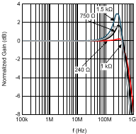
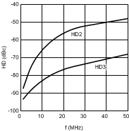
Unless otherwise specified, VS = ±2.5V, Rf = 240 Ω, RL = 100 Ω, VO = 2 VPP, COMP pin = HI, AV = +10 V/V, WSON-8 and SOT-23-5 packages (unless specifically noted).
| Vo = 2 Vpp | ||

| Vo = 2 Vpp | ||

| Vo = 0.2 Vpp | ||
WSON-8 Package

| Av = 10 V/V | ||
with Varying VO, WSON-8 Package

| Av = 10 V/V | Vs = +/-1.5 V | |
with Varying VO, WSON-8 Package

| Av = 4 V/V | COMP Pin = LO | |
with Varying VO, WSON-8 Package
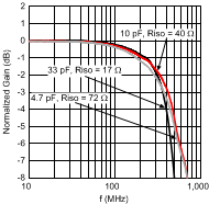
| RL = 100 Ω || CL | ||
| RISO as noted (measured @ CL) | ||


| VS = ±1.5 V | VO = 1 VPP | |

| 20 MHz | ||

| 1 MHz | ||

| 1 MHz | Vout = 2 Vpp | |
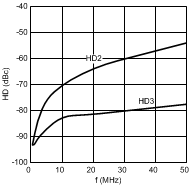
| Vo = 2 Vpp | ||
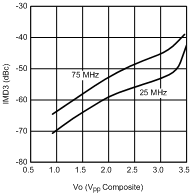
vs. Output Voltage
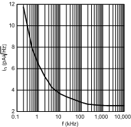


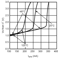
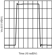
| AV= 4V/V | COMP Pin = LO | |

| Vs = 3.3 V | ||

| Vs = 3.3 V | ||

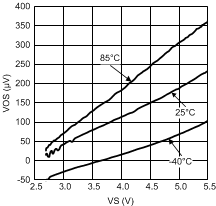
(Typical Unit)


| Vo = 1 Vpp | Vs = ±1.5V | |

| Vo = 1 Vpp | Vs = ±1.5 V | |

| Vo = 0.2 Vpp | ||
SOT-23-5 Package

| Av=10 V/V | ||
with Varying VO, SOT-23-5 Package

| Av=10 V/V | Vs= +/-1.5 V | |
with Varying VO, SOT-23-5 Package

| Av = 4 V/V | Vs = ±1.5 V | COMP Pin = LO |
with Varying VO, WSON-8 Package
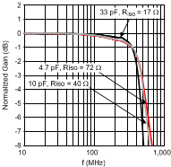
| RL = 100 Ω || CL, AV = 4 V/V | ||
| COMP Pin = LO | ||
| RISO as noted (measured @ CL) | ||
WSON-8 Package

| VS = ± 1.5 V | VO = 1 VPP | |

| 20 MHz | ||

| 1 MHz | ||

| 1 MHz | Vout = 2 Vpp | |
| Vo = 2 Vpp | ||


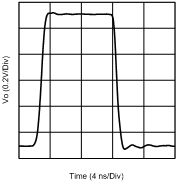


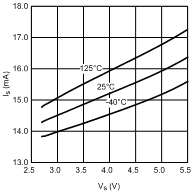

(Typical Unit)
7 Detailed Description
7.1 Overview
The LMH6629 is a high gain bandwidth, ultra low-noise voltage feedback operational amplifier. The excellent noise and bandwidth enables applications such as medical diagnostic ultrasound, magnetic tape and disk storage and fiberoptics to achieve maximum high frequency signal-to-noise ratios. The following discussion will enable the proper selection of external components to achieve optimum system performance.
7.2 Functional Block Diagram
The LMH6629 (WSON-8 package only) has some additional features to allow maximum flexibility. As shown in Figure 48, there are provisions for low-power shutdown and two internal compensation settings, which are discussed in more detail in Compensation. Also provided is a feedback (FB) pin which allows the placement of the feedback resistor directly adjacent to the inverting input (IN-) pin. This pin simplifies printed circuit board layout and minimizes the possibility of unwanted interaction between the feedback path and other circuit elements.
 Figure 48. 8-Pin WSON Pinout Diagram
The WSON-8 package requires the bottom-side Die Attach Paddle (DAP) to be soldered to the circuit board for proper thermal dissipation and to get the thermal resistance number specified. The DAP is tied to the V- potential within the LMH6629 package. Thus, the circuit board copper area devoted to DAP heatsinking connection should be at the V- potential as well. Please refer to the package drawing for the recommended land pattern and recommended DAP connection dimensions.
 Figure 49. WSON–8 DAP(Top View)
7.3 Feature Description
7.3.1 WSON-8 Control Pins and SOT-23-5 Comparison
The LMH6629 WSON-8 package has two digital control pins; PD and COMP pins. The PD pin, used for power down, floats high (device on) when not driven. When the PD pin is pulled low, the amplifier is disabled and the amplifier output stage goes into a high impedance state so the feedback and gain set resistors determine the output impedance of the circuit. The other control pin, the COMP pin, allows control of the internal compensation and defaults to the lower gain mode or logic 0.
The SOT-23-5 package has the following differences relative to the WSON-8 package:
- No power down (shutdown) capability.
- No COMP pin to set the minimum stable gain. SOT-23–5 package minimum stable gain is internally fixed to be 10V/V.
- No feedback (FB) pin.
From a performance point of view, the WSON-8 and the SOT-23-5 packages perform very similarly except in the following areas:
- SSBW, Peaking, and 0.1 dB Bandwidth: These differences are highlighted in the Typical Performance Characteristics and the Electrical Characteristics 5V tables. Most notable differences are with small signal (0.2 Vpp) and close to the minimum stable gain of 10V/V.
- Distortion: It is possible to get slightly different distortion performance. The board layout and decoupling capacitor return current routing strongly influence distortion performance.
- Output Current: In heavy current applications, there will be differences between these package types because of the difference in their respective Thermal Resistances (RθJA).
7.3.2 Compensation
The LMH6629 has two compensation settings that can be controlled by the COMP pin (WSON-8 package only). The default setting is set through an internal pulldown resistor and places the COMP pin at the logic 0 state. In this configuration the on-chip compensation is set to the maximum and bandwidth is reduced to enable stability at gains as low as 4V/V.
When this pin is driven to the logic 1 state, the internal compensation is decreased to allow higher bandwidth at higher gains. In this state, the minimum stable gain is 10V/V. Due to the reduced compensation, slew rate and large signal bandwidth are significantly enhanced for the higher gains.
NOTE
As mentioned earlier, the SOT-23-5 package does not offer the two compensation settings that the WSON-8 offers. The SOT-23-5 is internally set for a minimum gain of 10 V/V.
It is possible to externally compensate the LMH6629 for any of the following reasons, as shown in Figure 50.
- To operate the SOT-23-5 package (which does not offer the COMP pin) at closed loop gains < 10V/V.
- To operate the WSON-8 package at gains below the minimum stable gain of 4V /V when the COMP pin is LO. NOTE: In this case, Figure 50 “Constraint 1” may be changed to ≥ 4 V/V instead of ≥ 10 V/V.
- To operate either package at low gain and need maximum slew rate (COMP pin HI).
 Figure 50. External Compensation
This circuit operates by increasing the Noise Gain (NG) beyond the minimum stable gain of the LMH6629 while maintaining a positive loop gain phase angle at 0 dB. There are two constraints shown in Figure 50: “Constraint 1” ensures that NG has increased to at least 10 V/V when the loop gain approaches 0dB, and “Constraint 2” places an upper limit on the feedback phase lead network frequency to make sure it is fully effective in the frequency range when loop gain approaches 0dB. These two constraints allow one to estimate the “starting value” for Rc and Cc which may need to be fine tuned for proper response.
Here is an example worked out for more clarification:
- Assume that the objective is to use the SOT-23-5 version of the LMH6629 for a closed loop gain of +3.7 V/V using the technique shown in Figure 50.
- Selecting Rf = 249 Ω → Rg = 91 Ω → REQ= 66.6 Ω.
- For 50-Ω source termination (Rs= 50 Ω), select RT= 50 Ω → Rp = 25 Ω.
- Using “Constraint 1” (= 10V/V) allows one to compute Rc ≊ 56 Ω. Using “Constraint 2” (= 90 MHz) defines the appropriate value of Cc ≊ 33 pF.
- The frequency response plot shown in Figure 51 is the measured response with Rc and Cc values computed above and shows a -3 dB response of about 1 GHz.

| Cf = 1.5 pF | ||
| RA = 33 Ω | ||
| RB = 91 Ω |
with External Compensation
For the Figure 51 measured results, a compensation capacitor (Cf') was used across Rf to compensate for the summing node net capacitance due to the board and the SOT-23–5 LMH6629. The RA and RB combination reduces the effective capacitance of Cf‘ by the ratio of 1+RB / RA, with the constraint that RB << Rf, thereby allowing a practical capacitance value (> 1pF) to be used. The WSON-8 package does not need this compensation across Rf due to its lower parasitics.
With the COMP pin HI (WSON-8 package only) or with the SOT-23–5 package, this circuit achieves high slew rate and takes advantage of the LMH6629’s superior low-noise characteristics without sacrificing stability, while enabling lower gain applications. It should be noted that the Rc, Cc combination does lower the input impedance and increases noise gain at higher frequencies. With these values, the input impedance reduces by 3 dB at 490 MHz. The Noise Gain transfer function “zero” is given by Equation 1 and it has a 3-dB increase at 32.8 MHz with these values:
External Compensation Noise Gain Increase:

7.3.3 Cancellation of Offset Errors Due to Input Bias Currents
The LMH6629 offers exceptional offset voltage accuracy. In order to preserve the low offset voltage errors, care must be taken to avoid voltage errors due to input bias currents. This is important in both inverting and non-inverting applications.
The non-inverting circuit is used here as an example. To cancel the bias current errors of the non-inverting configuration, the parallel combination of the gain setting (Rg) and feedback (Rf) resistors should equal the equivalent source resistance (Rseq) as defined in Figure 52. Combining this constraint with the non-inverting gain equation also seen in Figure 52 allows both Rf and Rg to be determined explicitly from Equation 2:
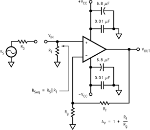 Figure 52. Non-Inverting Amplifier Configuration
When driven from a 0-Ω source, such as the output of an op amp, the non-inverting input of the LMH6629 should be isolated with at least a 25-Ω series resistor.
As seen in Figure 53, bias current cancellation is accomplished for the inverting configuration by placing a resistor (Rb) on the non-inverting input equal in value to the resistance seen by the inverting input (Rf || (Rg+Rs)). Rb should to be no less than 25 Ω for optimum LMH6629 performance. A shunt capacitor (not shown) can minimize the additional noise of Rb.
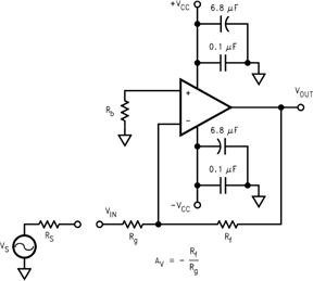 Figure 53. Inverting Amplifier Configuration
7.3.4 Total Input Noise vs. Source Resistance
To determine maximum signal-to-noise ratios from the LMH6629, an understanding of the interaction between the amplifier’s intrinsic noise sources and the noise arising from its external resistors is necessary. Figure 54 describes the noise model for the non-inverting amplifier configuration showing all noise sources. In addition to the intrinsic input voltage noise (en) and current noise (in = in+ = in−) source, there is also thermal voltage noise (et = √(4KTR)) associated with each of the external resistors.
 Figure 54. Non-Inverting Amplifier Noise Model
Equation 3 provides the general form for total equivalent input voltage noise density (eni).
General Noise Equation:

Equation 4 is a simplification of Equation 3 that assumes Rf || Rg = Rseq for bias current cancellation:

Figure 55 schematically shows eni alongside VIN (the portion of VS source which reaches the non-inverting input of Figure 52) and external components affecting gain (Av= 1 + Rf / Rg), all connected to an ideal noiseless amplifier.
 Figure 55. Non-Inverting Amplifier Equivalent Noise Source Schematic
Figure 56 illustrates the equivalent noise model using this assumption. Figure 57 is a plot of eni against equivalent source resistance (Rseq) with all of the contributing voltage noise source of Equation 4. This plot gives the expected eni for a given (Rseq) which assumes Rf||Rg = Rseq for bias current cancellation. The total equivalent output voltage noise (eno) is eni*AV.
 Figure 56. Noise Model with Rf||Rg = Rseq
As seen in Figure 57, eni is dominated by the intrinsic voltage noise (en) of the amplifier for equivalent source resistances below 15 Ω. Between 15 Ω and 2.5 kΩ, eni is dominated by the thermal noise (et = √(4kT(2Rseq)) of the equivalent source resistance Rseq. Incidentally, this is the range of Rseq values where the LMH6629 has the best (lowest) Noise Figure (NF) for the case where Rseq = Rf || Rg.
Above 2.5 kΩ, eni is dominated by the amplifier’s current noise (in = √2 * inRseq). When Rseq = 190 Ω (that is, Rseq = en/√2 * in), the contribution from voltage noise and current noise of LMH6629 is equal. For example, configured with a gain of +10V/V giving a −3dB of 825 MHz and driven from Rseq = Rf || Rg = 20 Ω (eni = 1.07 nV√Hz from Figure 57), the LMH6629 produces a total equivalent output noise voltage (eni * 10 V/V * √(1.57 * 825 MHz)) of 385 μVrms.

| RSEQ = RF || RG | ||
If bias current cancellation is not a requirement, then Rf || Rg does not need to equal Rseq. In this case, according to Equation 3, Rf || Rg should be as low as possible to minimize noise. Results similar to Equation 3 are obtained for the inverting configuration of Figure 53 if Rseq is replaced by Rb and Rg is replaced by Rg + Rs. With these substitutions, Equation 3 will yield an eni referred to the non-inverting input. Referring eni to the inverting input is easily accomplished by multiplying eni by the ratio of non-inverting to inverting gains (1+Rg/ Rf).
7.3.5 Noise Figure
Noise Figure (NF) is a measure of the noise degradation caused by an amplifier.
General Noise Figure Equation:

Looking at the two parts of the NF expression (inside the log function) yields:
- Si/ So→ Inverse of the power gain provided by the amplifier
- No/ Ni→ Total output noise power, including the contribution of RS, divided by the noise power at the input due to RS
To simplify this, consider Na as the noise power added by the amplifier (reflected to its input port):
- Si/ So→ 1/ G
- No/ Ni→ G * (Ni+Na) / Ni (where G*(Ni +Na ) = No)
Substituting these two expressions into the NF expression:

The noise figure expression has simplified to depend only on the ratio of the noise power added by the amplifier at its input (considering the source resistor to be in place but noiseless in getting Na) to the noise power delivered by the source resistor (considering all amplifier elements to be in place but noiseless in getting Ni).
For a given amplifier with a desired closed loop gain, to minimize noise figure:
- Minimize Rf || Rg
- Choose the Optimum RS (ROPT)
ROPT is the point at which the NF curve reaches a minimum and is approximated by:
Figure 58 is a plot of NF vs RS with the circuit of Figure 52 (Rf = 240 Ω, AV = +10V/V). The NF curves for both Unterminated (RT = open) and Terminated systems (RT = RS) are shown. Table 1 indicates NF for various source resistances including RS = ROPT.

| f > 1 MHz | ||
Table 1. Noise Figure for Various Rs
| RS (Ω) | NF (TERMINATED) (dB) | NF (UNTERMINATED) (dB) |
|---|---|---|
| 50 | 8 | 3.2 |
| ROPT | 4.1 (ROPT = 750 Ω) |
1.1 (ROPT = 350 Ω) |
7.3.6 Single-Supply Operation
The LMH6629 can be operated with single power supply as shown in Figure 59. Both the input and output are capacitively coupled to set the DC operating point.
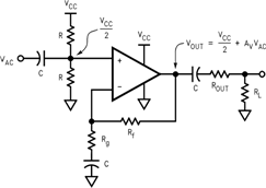 Figure 59. Single-Supply Operation
7.3.7 Low-Noise Transimpedance Amplifier
Figure 60 implements a high-speed, single-supply, low-noise Transimpedance amplifier commonly used with photo-diodes. The transimpedance gain is set by RF.
 Figure 60. 200 MHz Transimpedance Amplifier Configuration
Figure 61 shows the Noise Gain (NG) and transfer function (I-V Gain). As with most Transimpedance amplifiers, it is required to compensate for the additional phase lag (Noise Gain zero at fZ) created by the total input capacitance ( CD (diode capacitance) + CCM (LMH6629 CM input capacitance) + CDIFF (LMH6629 DIFF input capacitance) ) looking into RF. This is accomplished by placing CF across RF to create enough phase lead (Noise Gain pole at fP) to stabilize the loop.
 Figure 61. Transimpedance Amplifier Noise Gain and Transfer Function
The optimum value of CF is given by Equation 8 resulting in the I-V -3dB bandwidth shown in Equation 9, or around 200 MHz in this case (assuming GBWP= 4GHz with COMP pin = HI for WSON-8 package). This CF value is a “starting point” and CF needs to be tuned for the particular application as it is often less than 1 pF and thus is easily affected by board parasitics. For maximum speed, the LMH6629 COMP pin should be HI (or use the SOT-23 package).
Optimum CF Value:

Resulting -3dB Bandwidth

Equation 10 provides the total input current noise density (ini) equation for the basic Transimpedance configuration and is plotted against feedback resistance (RF) showing all contributing noise sources in Figure 62. The plot indicates the expected total equivalent input current noise density (ini) for a given feedback resistance (RF). This is depicted in the schematic of Figure 63 where total equivalent current noise density (ini) is shown at the input of a noiseless amplifier and noiseless feedback resistor (RF). The total equivalent output voltage noise density (eno) is ini*RF.
Noise Equation for Transimpedance Amplifier:

 Figure 62. Current Noise Density vs. Feedback Resistance
 Figure 63. Transimpedance Amplifier Equivalent Input Source Model
From Figure 62, it is clear that with LMH6629’s extremely low-noise characteristics, for RF < 2.5 kΩ, the noise performance is entirely dominated by RF thermal noise. Only above this RF threshold, LMH6629’s input noise current (in) starts being a factor and at no RF setting does the LMH6629 input noise voltage play a significant role. This noise analysis has ignored the possible noise gain increase, due to photo-diode capacitance, at higher frequencies.
7.3.8 Low-Noise Integrator
Figure 64 shows a deBoo integrator implemented with the LMH6629. Positive feedback maintains integration linearity. The LMH6629’s low input offset voltage and matched inputs allow bias current cancellation and provide for very precise integration. Keeping RG and RS low helps maintain dynamic stability.
 Figure 64. Low-Noise Integrator
7.3.9 High-Gain Sallen-Key Active Filters
The LMH6629 is well suited for high-gain Sallen-Key type of active filters. Figure 65 shows the 2nd order Sallen-Key low-pass filter topology. Using component predistortion methods discussed in OA-21, Component Pre-Distortion for Sallen Key Filters (SNOA369), enables the proper selection of components for these high-frequency filters.
 Figure 65. Low Pass Sallen-Key Active Filter Topology
7.4 Device Functional Modes
With an industry-leading low noise voltage operating off a supply voltage as low as 2.7-V and a common mode input voltage range that extends 0.3 V below V−, the LMH6629 finds applications in single supply, high bandwidth, ultra-low noise applications. With a GBWP of 4GHz, the LMH6629 can operate at large gains and deliver exceptional speed and low noise. Choose the WSON(8) package for the ultimate flexibility (including Power Down and COMP pin which allows tailoring internal compensation to the operating gain conditions), or the SOT23-5 package if Power Down is not needed and closed loop gain is ≥ 20dB.
8 Application and Implementation
NOTE
Information in the following applications sections is not part of the TI component specification, and TI does not warrant its accuracy or completeness. TI’s customers are responsible for determining suitability of components for their purposes. Customers should validate and test their design implementation to confirm system functionality.
8.1 Application Information
The following discussion details some of the applications that can benefit from the LMH6629’s ultra-low noise, wide bandwidth, and single supply capability.
Note that It is essential to use a low-noise / low-distortion device to drive a high resolution ADC. This will minimize the impact on the quantization noise and to make sure that the driver’s distortion does not dominate the acquired data.
Equation 11 demonstrates the converter noise expression and Equation 12 shows the converter noise expression evaluated for the example depicted in Figure 66. Figure 67 shows a high-performance low-noise equalizer for such applications as magnetic tape channels using the LMH6629. Figure 68 shows the circuit’s simulated frequency response.
8.2 Typical Application
Many high-resolution data converters (ADC’s) require a differential input driver. In order to preserve the ADC’s dynamic range, the analog input driver must have a noise floor which is lower than the ADC’s noise floor. Figure 66 shows a ground referenced bipolar input (symmetrical swing around 0V) SE to differential converter used to drive a high resolution ADC. The combination of LMH6629’s low noise and the converter architecture reduces the impact on the ADC noise.
 Figure 66. Low-Noise Single-Ended (SE) to Differential Converter
8.2.1 Design Requirements
For an ADC with N bits, the quantization Signal-to-noise ratio (SNR) is 6.02* N + 1.76 in dB. For example, a 12-bit ADC has a SNR of 74 dB (= 5000 V/V). Assuming a full-scale differential input of 2Vpp (0.707 V_RMS), the quantization oise referred to the ADC’s input is ~140 μV_RMS (= 0.707 V_RMS / 5000 V/V) over the bandwidth “visible” to the ADC. Assuming an ADC input bandwidth of 20 MHz, this translates to just 25 nV/RtHz (= 141 µV_RMS / SQRT(20 MHz * π/2)) noise density at the output of the driver. Using an amplifier to form the single-ended (SE) to Differential converter / driver for such an application is challenging, especially when there is some gain required. In addition, the input driver’s linearity (harmonic distortion) must also be high enough such that the spurs that get through to the ADC input are below the ADC’s LSB threshold or -73 dBc (= 20*log (1/ 212)) or lower in this case. Therefore, it is essential to use a low-noise / low-distortion device to drive a high resolution ADC in order to minimize the impact on the quantization noise and to make sure that the driver’s distortion does not dominate the acquired data.
8.2.2 Detailed Design Procedure
In the circuit depicted in Figure 66, the required gain dictates the resistor ratio “K”. With “K” and the driver output CM voltage (VO_CM) known, VSET can be established. Reasonable values for Rf and Rg can be set to complete the design.
In terms of output swing, with the LMH6629 output swing capability which requires ~0.85 V of headroom from either rail, the maximum total output swing into the ADC is limited to 6.6 VPP (=(5 – 2 x 0.85V) x 2); that is true with VO_CM set to mid-rail between V+ and V-. It should also be noted that the LMH6629’s input CMVR range includes the lower rail (V-) and that is the reason there is great flexibility in setting Vo_CM by controlling VSET. Another feature is that A1 and A2 inputs act like “virtual grounds” and thus do not see any signal swing. Note that due to the converter’s biasing, the source, VIN, needs to sink a current equal to VSET / RIN.
The converter example shown in Figure 66 operates with a noise gain of 6 (=1+ K / 2) and thus requires that the COMP pin to be tied low (WSON-8 package only). The 1st order approximated small signal bandwidth will be 280 MHz (=1.7 GHz / 6 V/V) which is computed using 1.7 GHz as the GBWP with COMP pin LO.
From a noise point of view, concentrating only on the dominant noise sources involved, here is the expression for the expected differential noise density at the input of the ADC.
Converter Noise Expression:

en is the LMH6629 input noise voltage and eRin_thermal is the thermal noise of RIN. The “23” and the “22” multipliers account for the different instances of each noise source (2 for en, and 1 for eRin_thermal).
Equation 11, evaluated for the circuit example of Figure 66, is shown in Equation 12:

Because of the LMH6629’s low input noise voltage (en), noise is dominated by the thermal noise of RIN. It is evident that the input resistor, RIN, can be reduced to lower the noise with lower input impedance as the trade-off.
8.2.2.1 Low-Noise Magnetic Media Equalizer
Figure 67 shows a high-performance low-noise equalizer for such applications as magnetic tape channels using the LMH6629. The circuit combines an integrator (used to limit noise) with a bandpass filter (used to boost the response centered at a frequency or over a band of interest) to produce the low-noise equalization. The circuit’s simulated frequency response is illustrated in Figure 68.
In this circuit, the bandpass filter center frequency is set by Equation 13:

For higher selectivity, use high C values; for wider bandwidth, use high L values, while keeping the product of L and C values the same to keep fc intact. The integrator’s -3dB roll-off is set by

If:

The integrator and the bandpass filter frequency interaction is minimized so that the operating frequencies of each can be set independently. Lowering the value of R2 increases the bandpass gain (boost) without affecting the integrator frequencies. With the LMH6629’s wide Gain Bandwidth (4 GHz), the center frequency could be adjusted higher without worries about loop gain limitation. This increases flexibility in tuning the circuit.
 Figure 67. Low-Noise Magnetic Media Equalizer
8.2.3 Application Curves
 Figure 68. Equalizer Frequency Response