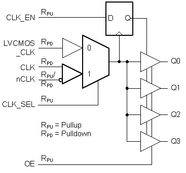
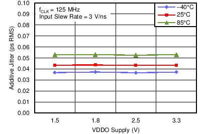
The LMK00804B is a low skew, high performance clock fanout buffer which can distribute up to four LVCMOS/LVTTL outputs (3.3-V, 2.5-V, 1.8-V, or 1.5-V levels) from one of two selectable inputs, which can accept differential or single-ended inputs. The clock enable input is synchronized internally to eliminate runt or glitch pulses on the outputs when the clock enable terminal is asserted or de-asserted. The outputs are held in logic low state when the clock is disabled. A separate output enable terminal controls whether the outputs are active state or high-impedance state. The low additive jitter and phase noise floor, and guaranteed output and part-to-part skew characteristics make the LMK00804B ideal for applications demanding high performance and repeatability.
See also Device Comparison Table for descriptions of CDCLVC1310 and LMK00725 parts.
PART NUMBER | PACKAGE | BODY SIZE (NOM) |
---|---|---|
LMK00804B | TSSOP (16) | 5.00 mm × 4.40 mm |
PART NUMBER | DESCRIPTION |
---|---|
CDCLVC1310 | 10 outputs LVCMOS fanout buffer with Diff, Single-Ended, or Crystal Input |
LMK00725 | 5 output LVPECL fanout buffer with Differential or Single-Ended Input |
TERMINAL | TYPE(1) | DESCRIPTION | |
---|---|---|---|
NAME | NUMBER | ||
GND | 1, 9, 13 | G | Power supply ground |
OE | 2 | I, RPU | Output enable input. 0 = Outputs in Hi-Z state 1 = Outputs in active state |
VDD | 3 | P | Power supply terminal |
CLK_EN | 4 | I, RPU | Synchronous clock enable input. 0 = Outputs are forced to logic low state 1 = Outputs are enabled with LVCMOS/LVTT levels |
CLK | 5 | I, RPD | Non-inverting differential clock input 0. |
nCLK | 6 | I, RPD/RPU | Inverting differential clock input 0. Internally biased to VDD/2 when left floating |
CLK_SEL | 7 | I, RPU | Clock select input. 0 = Select LVCMOS_CLK 1 = Select CLK, nCLK |
LVCMOS_CLK | 8 | I, RPD | Single-ended clock input. Accepts LVCMOS/LVTTL levels. |
Q3, Q2, Q1, Q0 | 10, 12, 14, 16 | O | Single-ended clock outputs with LVCMOS/LVTTL levels, 7Ω output impedance |
VDDO | 11, 15 | P | Output supply terminals |
MIN | TYP | MAX | UNIT | |||
---|---|---|---|---|---|---|
CIN | Input Capacitance | 1 | pF | |||
RPU | Input Pullup Resistance | 51 | kΩ | |||
RPD | Input Pulldown Resistance | 51 | kΩ | |||
CPD | Power Dissipation Capacitance (per output) | 2 | pF | |||
ROUT | Output impedance | 7 | Ω |
MIN | TYP | MAX | UNIT | |||
---|---|---|---|---|---|---|
VDD | Core Supply Voltage | –0.3 | 3.6 | V | ||
VDDO | Output Supply Voltage | –0.3 | 3.6 | V | ||
VIN | Input Voltage Range | –0.3 | VDD +0.3 |
V | ||
TJ | Junction Temperature | 150 | °C |
MIN | MAX | UNIT | |||
---|---|---|---|---|---|
Tstg | Storage temperature range | –65 | 150 | °C | |
V(ESD) | Electrostatic discharge(3) | Human body model (HBM), per ANSI/ESDA/JEDEC JS-001, all pins(1) | 1000 | V | |
Charged device model (CDM), per JEDEC specification JESD22-C101, all pins(2) | 250 |
MIN | TYP | MAX | UNIT | ||||
---|---|---|---|---|---|---|---|
VDD | Core Supply Voltage | 3.135 | 3.3 | 3.465 | V | ||
VDDO | Output Supply Voltage | 3.135 | 3.3 | 3.465 | V | ||
2.375 | 2.5 | 2.625 | |||||
1.65 | 1.8 | 1.95 | |||||
1.425 | 1.5 | 1.575 | |||||
TA | Ambient Temperature | -40 | 85 | °C | |||
TJ | Junction Temperature | 125 | °C |
THERMAL METRIC(1) | MIN | TYP | MAX | UNIT | ||
---|---|---|---|---|---|---|
R θJA | Package Thermal Impedance, Junction to Air (0 LFPM) | 116 | °C/W |
PARAMETER | MIN | TYP | MAX | UNIT | |||
---|---|---|---|---|---|---|---|
IDD | Power Supply Current through VDD | 21 | mA | ||||
IDDO | Power Supply Current through VDDO | 5 | mA |
PARAMETER | TEST CONDITIONS | MIN | TYP | MAX | UNIT | ||
---|---|---|---|---|---|---|---|
VIH | Input High Voltage | CLK_EN, CLK_SEL, OE |
2 | VDD + 0.3 | V | ||
LVCMOS_CLK | 2 | VDD + 0.3 | V | ||||
VIL | Input Low Voltage | CLK_EN, CLK_SEL, OE |
–0.3 | 0.8 | V | ||
LVCMOS_CLK | –0.3 | 1.3 | |||||
IIH | Input High Current | CLK_EN, CLK_SEL, OE |
VDD = 3.465 V, VIN = 3.465 V |
5 | µA | ||
LVCMOS_CLK | VDD = 3.465 V, VIN = 3.465 V |
150 | |||||
IIL | Input Low Current | CLK_EN, CLK_SEL, OE |
VDD = 3.465 V, VIN = 0 V |
–150 | µA | ||
LVCMOS_CLK | VDD = 3.465 V, VIN = 0 V |
–5 | |||||
VOH | Output High Voltage(1) | VDDO = 3.3 V ± 5% | 2.6 | V | |||
VDDO = 2.5 V ± 5% | 1.8 | ||||||
VDDO = 1.8 V ± 0.15 V | 1.5 | ||||||
VDDO = 1.5 V ± 5% | VDDO – 0.3 | ||||||
VOL | Output Low Voltage(1) | VDDO = 3.3 V ± 5% | 0.5 | V | |||
VDDO = 2.5 V ± 5% | 0.5 | ||||||
VDDO = 1.8 V ± 0.15 V | 0.4 | ||||||
VDDO = 1.5 V ± 5% | 0.35 | ||||||
IOZL | Output Hi-Z Current Low | –5 | µA | ||||
IOZH | Output Hi-Z Current High | 5 |
PARAMETER | TEST CONDITIONS | MIN | TYP | MAX | UNIT | ||
---|---|---|---|---|---|---|---|
VID | Differential Input Voltage Swing, (VIH-VIL)(1) |
0.15 | 1.3 | V | |||
VICM | Input Common Mode Voltage(1)(2) | 0.5 | VDD – 0.85 | V | |||
IIH | Input High Current(3) | nCLK | VDD = 3.465 V, VIN = 3.465 V |
150 | µA | ||
CLK | VDD = 3.465 V, VIN = 3.465 V |
150 | |||||
IIL | Input Low Current(3) | nCLK | VDD = 3.465 V , VIN = 0 V |
-150 | µA | ||
CLK | VDD = 3.465 V, VIN = 0 V |
-5 |
PARAMETER | TEST CONDITIONS | MIN | TYP | MAX | UNIT | ||
---|---|---|---|---|---|---|---|
fOUT | Maximum Output Frequency(11)(1) | 350 | MHz | ||||
tPDLH | Propagation Delay, Low to High(9) |
LVCMOS_CLK(2), CLK/nCLK(3) |
0°C to 70°C | 1.1 | 2.1 | ns | |
–40°C to 85°C | 0.95 | 2.2 | ns | ||||
tSK(O) | Output Skew(1)(4)(5) | Measured on rising edge | 35 | ps | |||
tSK(PP) | Part-to-Part Skew(9)(5)(6) | 700 | ps | ||||
tR/tF | Output Rise/Fall Time(9) | 20% to 80% | 50 | 700 | ps | ||
JADD | Additive Jitter(7) | f=125 MHz, Input slew rate ≥ 3 V/ns, 12 kHz to 20 MHz integration band |
0.04 | ps RMS | |||
PNFLOOR | Phase Noise Floor(8) | f = 125 MHz, Input slew rate ≥ 3 V/ns |
dBc/Hz | ||||
10 kHz offset | -155 | ||||||
100 kHz offset | -162 | ||||||
1 MHz offset | -166 | ||||||
10 MHz offset | -166 | ||||||
20 MHz offset | -166 | ||||||
ODC | Output Duty Cycle(9)(10) | REF = CLK/nCLK | 45% | 55% | |||
REF = LVCMOS_CLK, f ≤ 300 MHz |
45% | 55% | |||||
tEN | Output Enable Time | 5 | ns | ||||
tDIS | Output Disable Time | 5 | ns |
PARAMETER | TEST CONDITIONS | MIN | TYP | MAX | UNIT | ||
---|---|---|---|---|---|---|---|
fOUT | Maximum Output Frequency(10)(1) | 350 | MHz | ||||
tPDLH | Propagation Delay, Low to High(8) |
LVCMOS_CLK(2), CLK/nCLK(3) |
0°C to 70°C | 1.1 | 2.1 | ns | |
–40°C to 85°C | 0.95 | 2.2 | |||||
tSK(O) | Output Skew(1)(4)(5) | Measured on rising edge | 35 | ps | |||
tSK(PP) | Part-to-Part Skew(8)(5)(6) | 700 | ps | ||||
tR/tF | Output Rise/Fall Time(8) | 20% to 80% | 50 | 700 | ps | ||
JADD | Additive Jitter(7) | f=125 MHz, Input slew rate ≥ 3 V/ns, 12 kHz to 20 MHz integration band |
0.04 | ps RMS | |||
ODC | Output Duty Cycle(8)(9) | REF = CLK/nCLK | 45% | 55% | |||
REF = LVCMOS_CLK, f ≤ 300 MHz |
45% | 55% | |||||
tEN | Output Enable Time | 5 | ns | ||||
tDIS | Output Disable Time | 5 | ns |
PARAMETER | TEST CONDITIONS | MIN | TYP | MAX | UNIT | ||
---|---|---|---|---|---|---|---|
fOUT | Maximum Output Frequency(10)(1) | 350 | MHz | ||||
tPDLH | Propagation Delay, Low to High(8) |
LVCMOS_CLK(2), CLK/nCLK(3) |
0°C to 70°C | 1.1 | 2.2 | ns | |
–40°C to 85°C | 0.95 | 2.3 | ns | ||||
tSK(O) | Output Skew(1)(4)(5) | Measured on rising edge | 35 | ps | |||
tSK(PP) | Part-to-Part Skew(8)(5)(6) | 700 | ps | ||||
tR/tF | Output Rise/Fall Time(8) | 20% to 80% | 100 | 700 | ps | ||
JADD | Additive Jitter(7) | f=125 MHz, Input slew rate ≥ 3 V/ns, 12 kHz to 20 MHz integration band |
0.04 | ps RMS | |||
ODC | Output Duty Cycle(8)(9) | REF = CLK/nCLK | 45% | 55% | |||
REF = LVCMOS_CLK, f ≤ 300 MHz |
45% | 55% | |||||
tEN | Output Enable Time | 5 | ns | ||||
tDIS | Output Disable Time | 5 | ns |
PARAMETER | TEST CONDITIONS | MIN | TYP | MAX | UNIT | ||
---|---|---|---|---|---|---|---|
fOUT | Maximum Output Frequency(10)(1) | 350 | MHz | ||||
tPDLH | Propagation Delay, Low to High(8) |
LVCMOS_CLK(2), CLK/nCLK(3) |
0°C to 70°C | 1.1 | 2.2 | ns | |
–40°C to 85°C | 0.95 | 2.3 | ns | ||||
tSK(O) | Output Skew(1)(4)(5) | Measured on rising edge | 35 | ps | |||
tSK(PP) | Part-to-Part Skew(1)(5)(6) | 1 | ns | ||||
tR/tF | Output Rise/Fall Time(8) | 20% to 80% | 100 | 900 | ps | ||
JADD | Additive Jitter(7) | f=125 MHz, Input slew rate ≥ 3 V/ns, 12 kHz to 20 MHz integration band |
0.04 | ps RMS | |||
ODC | Output Duty Cycle(8)(9) | f ≤ 166 MHz | 45% | 55% | |||
f > 166 MHz | 42% | 58% | |||||
tEN | Output Enable Time | 5 | ns | ||||
tDIS | Output Disable Time | 5 | ns |