SNAS688C Februray 2017 – May 2018 LMK04832
PRODUCTION DATA.
- 1 Features
- 2 Applications
- 3 Description
- 4 Revision History
- 5 Pin Configuration and Functions
- 6 Specifications
- 7 Parameter Measurement Information
-
8 Detailed Description
- 8.1 Overview
- 8.2 Functional Block Diagram
- 8.3 Feature Description
- 8.4 Device Functional Modes
- 8.5 Programming
- 8.6
Register Maps
- 8.6.1 Register Map for Device Programming
- 8.6.2
Device Register Descriptions
- 8.6.2.1 System Functions
- 8.6.2.2
(0x100 - 0x138) Device Clock and SYSREF Clock Output Controls
- 8.6.2.2.1 DCLKX_Y_DIV
- 8.6.2.2.2 DCLKX_Y_DDLY
- 8.6.2.2.3 CLKoutX_Y_PD, CLKoutX_Y_ODL, CLKoutX_Y_IDL, DCLKX_Y_DDLY_PD, DCLKX_Y_DDLY[9:8], DCLKX_Y_DIV[9:8]
- 8.6.2.2.4 CLKoutX_SRC_MUX, CLKoutX_Y_PD, DCLKX_Y_BYP, DCLKX_Y_DCC, DCLKX_Y_POL, DCLKX_Y_HS
- 8.6.2.2.5 CLKoutY_SRC_MUX, SCLKX_Y_PD, SCLKX_Y_DIS_MODE, SCLKX_Y_POL, SCLKX_Y_HS
- 8.6.2.2.6 SCLKX_Y_ADLY_EN, SCLKX_Y_ADLY
- 8.6.2.2.7 SCLKX_Y_DDLY
- 8.6.2.2.8 CLKoutY_FMT, CLKoutX_FMT
- 8.6.2.3
SYSREF, SYNC, and Device Config
- 8.6.2.3.1 VCO_MUX, OSCout_MUX, OSCout_FMT
- 8.6.2.3.2 SYSREF_REQ_EN, SYNC_BYPASS, SYSREF_MUX
- 8.6.2.3.3 SYSREF_DIV
- 8.6.2.3.4 SYSREF_DDLY
- 8.6.2.3.5 SYSREF_PULSE_CNT
- 8.6.2.3.6 PLL2_RCLK_MUX, PLL2_NCLK_MUX, PLL1_NCLK_MUX, FB_MUX, FB_MUX_EN
- 8.6.2.3.7 PLL1_PD, VCO_LDO_PD, VCO_PD, OSCin_PD, SYSREF_GBL_PD, SYSREF_PD, SYSREF_DDLY_PD, SYSREF_PLSR_PD
- 8.6.2.3.8 DDLYdSYSREF_EN, DDLYdX_EN
- 8.6.2.3.9 DDLYd_STEP_CNT
- 8.6.2.3.10 SYSREF_CLR, SYNC_1SHOT_EN, SYNC_POL, SYNC_EN, SYNC_PLL2_DLD, SYNC_PLL1_DLD, SYNC_MODE
- 8.6.2.3.11 SYNC_DISSYSREF, SYNC_DISX
- 8.6.2.3.12 PLL1R_SYNC_EN, PLL1R_SYNC_SRC, PLL2R_SYNC_EN
- 8.6.2.4
(0x146 - 0x149) CLKin Control
- 8.6.2.4.1 CLKin_SEL_PIN_EN, CLKin_SEL_PIN_POL, CLKin2_EN, CLKin1_EN, CLKin0_EN, CLKin2_TYPE, CLKin1_TYPE, CLKin0_TYPE
- 8.6.2.4.2 CLKin_SEL_AUTO_REVERT_EN, CLKin_SEL_AUTO_EN, CLKin_SEL_MANUAL, CLKin1_DEMUX, CLKin0_DEMUX
- 8.6.2.4.3 CLKin_SEL0_MUX, CLKin_SEL0_TYPE
- 8.6.2.4.4 SDIO_RDBK_TYPE, CLKin_SEL1_MUX, CLKin_SEL1_TYPE
- 8.6.2.5 RESET_MUX, RESET_TYPE
- 8.6.2.6
(0x14B - 0x152) Holdover
- 8.6.2.6.1 LOS_TIMEOUT, LOS_EN, TRACK_EN, HOLDOVER_FORCE, MAN_DAC_EN, MAN_DAC[9:8]
- 8.6.2.6.2 MAN_DAC
- 8.6.2.6.3 DAC_TRIP_LOW
- 8.6.2.6.4 DAC_CLK_MULT, DAC_TRIP_HIGH
- 8.6.2.6.5 DAC_CLK_CNTR
- 8.6.2.6.6 CLKin_OVERRIDE, HOLDOVER_EXIT_MODE, HOLDOVER_PLL1_DET, LOS_EXTERNAL_INPUT, HOLDOVER_VTUNE_DET, CLKin_SWITCH_CP_TRI, HOLDOVER_EN
- 8.6.2.6.7 HOLDOVER_DLD_CNT
- 8.6.2.7 (0x153 - 0x15F) PLL1 Configuration
- 8.6.2.8 (0x160 - 0x16E) PLL2 Configuration
- 8.6.2.9 (0x16F - 0x555) Misc Registers
- 9 Application and Implementation
- 10Power Supply Recommendations
- 11Layout
- 12Device and Documentation Support
- 13Mechanical, Packaging, and Orderable Information
Package Options
Mechanical Data (Package|Pins)
- NKD|64
Thermal pad, mechanical data (Package|Pins)
- NKD|64
Orderable Information
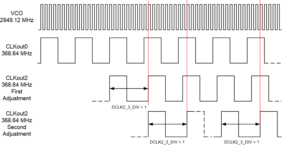
8.3.4.3 Single and Multiple Dynamic Digital Delay Example
In this example, two separate adjustments are made to the device clocks. In the first adjustment, a single delay of 1 VCO cycle occurs between CLKout2 and CLKout0. In the second adjustment, two delays of 1 VCO cycle occur between CLKout2 and CLKout0. At this point in the example, CLKout2 is delayed 3 VCO cycles behind CLKout0.
Assuming the device already has the following initial configurations:
- VCO frequency: 2949.12 MHz
- CLKout0 = 368.64 MHz, DCLK0_1_DIV = 8
- CLKout2 = 368.64 MHz, DCLK2_3_DIV = 8
The following steps illustrate the example above:
- Set DCLK2_3_DDLY = 4. First part of delay for CLKout2.
- Set DCLK2_3_DDLY_PD = 0. Enable the digital delay for CLKout2.
- Set DDLYd0_EN = 0 and DDLYd2_EN = 1. Enable dynamic digital delay for CLKout2 but not CLKout0.
- Set DDLYd_STEP_CNT = 1. This begins the first adjustment.
Before step 4, CLKout2 clock edge is aligned with CLKout0.
After step 4, CLKout2 counts nine clock distribution path cycles to the next rising edge, one greater than the divider value, effectively delaying CLKout2 by one VCO cycle with respect to CLKout0. This is the first adjustment.
5. Set DDLYd_STEP_CNT = 2. This begins the second adjustment.
Before step 5, CLKout2 clock edge was delayed 1 clock distribution path cycle from DCLKout0.
After step 5, CLKout2 counts nine clock distribution path cycles twice, each time one greater than the divide value, effectively delaying CLKout2 by two clock distribution path cycles with respect to CLKout0.This is the second adjustment.
 Figure 10. Single and Multiple Adjustment Dynamic Digital Delay Example