SNAS859 March 2024 LMK05318B-Q1
PRODUCTION DATA
- 1
- 1 Features
- 2 Applications
- 3 Description
- 4 Pin Configuration and Functions
- 5 Specifications
- 6 Parameter Measurement Information
-
7 Detailed Description
- 7.1 Overview
- 7.2 Functional Block Diagram
- 7.3
Feature Description
- 7.3.1 Oscillator Input (XO_P/N)
- 7.3.2 Reference Inputs (PRIREF_P/N and SECREF_P/N)
- 7.3.3 Clock Input Interfacing and Termination
- 7.3.4 Reference Input Mux Selection
- 7.3.5 Hitless Switching
- 7.3.6 Gapped Clock Support on Reference Inputs
- 7.3.7 Input Clock and PLL Monitoring, Status, and Interrupts
- 7.3.8
PLL Relationships
- 7.3.8.1 PLL Frequency Relationships
- 7.3.8.2 Analog PLLs (APLL1, APLL2)
- 7.3.8.3 APLL Reference Paths
- 7.3.8.4 APLL Phase Frequency Detector (PFD) and Charge Pump
- 7.3.8.5 APLL Feedback Divider Paths
- 7.3.8.6 APLL Loop Filters (LF1, LF2)
- 7.3.8.7 APLL Voltage Controlled Oscillators (VCO1, VCO2)
- 7.3.8.8 APLL VCO Clock Distribution Paths (P1, P2)
- 7.3.8.9 DPLL Reference (R) Divider Paths
- 7.3.8.10 DPLL Time-to-Digital Converter (TDC)
- 7.3.8.11 DPLL Loop Filter (DLF)
- 7.3.8.12 DPLL Feedback (FB) Divider Path
- 7.3.9 Output Clock Distribution
- 7.3.10 Output Channel Muxes
- 7.3.11 Output Dividers (OD)
- 7.3.12 Clock Outputs (OUTx_P/N)
- 7.3.13 Glitchless Output Clock Start-Up
- 7.3.14 Clock Output Interfacing and Termination
- 7.3.15 Output Synchronization (SYNC)
- 7.4 Device Functional Modes
- 7.5 Programming
- 8 Application and Implementation
- 9 Device and Documentation Support
- 10Revision History
- 11Mechanical, Packaging, and Orderable Information
Package Options
Refer to the PDF data sheet for device specific package drawings
Mechanical Data (Package|Pins)
- RGZ|48
Thermal pad, mechanical data (Package|Pins)
- RGZ|48
Orderable Information
7.4.4 Digitally-Controlled Oscillator (DCO) Mode
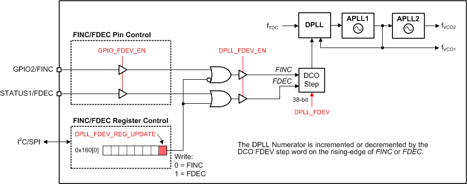
To support the IEEE 1588 peripheral clock and other clock steering applications, the DPLL supports DCO mode to allow precise output clock frequency adjustment of less than 0.001ppb/step. DCO mode can be enabled (DPLL_FDEV_EN = 1) when the DPLL is locked.
The DCO frequency step size can be programmed through a 38-bit frequency deviation word register (DPLL_FDEV bits). The DPLL_FDEV value is an offset added to or subtracted from the current numerator value of the DPLL fractional feedback divider and determines the DCO frequency offset at the VCO output.
The DCO frequency increment (FINC) or frequency decrement (FDEC) updates can be controlled through software control or pin control in I2C mode. DCO updates through software control are always available through I2C or SPI by writing to the DPLL_FDEV_REG_UPDATE register bit. Writing a 0 increments the DCO frequency by the programmed step size, and writing a 1 decrements the DCO frequency by the step size. SPI can achieve faster DCO update rates than to I2C because the SPI has faster register transfer.
When pin control mode is enabled (GPIO_FDEV_EN = 1) in I2C mode, the GPIO2/SDO/FINC pin functions as the FINC input and the STATUS1/FDEC pin functions as the FDEC input (STATUS1 output is disabled). A positive pulse on the FINC pin or FDEC pin applies a corresponding DCO update to the DPLL. The minimum positive pulse width applied to the FINC or FDEC pins must be greater than 100ns to be captured by the internal sampling clock. The DCO update rate must be limited to less than 1MHz when using pin control.
When DCO mode is disabled (DPLL_FDEV_EN = 0), the DCO frequency offset is cleared and the VCO output frequency is determined by the original numerator value of the DPLL fractional feedback divider.
 Figure 7-34 DCO Mode Control Options