SNVS829E March 1999 – February 2017 LMP8480 , LMP8481
PRODUCTION DATA.
- 1 Features
- 2 Applications
- 3 Description
- 4 Revision History
- 5 Device Comparison Table
- 6 Pin Configuration and Functions
- 7 Specifications
-
8 Detailed Description
- 8.1 Overview
- 8.2 Functional Block Diagrams
- 8.3
Feature Description
- 8.3.1 Basic Connections
- 8.3.2 Selection of the Sense Resistor
- 8.3.3 Using PCB Traces as Sense Resistors
- 8.3.4 VREFA and VREFB Pins (LMP8481 Only)
- 8.3.5 Reference Input Voltage Limits (LMP8481 Only)
- 8.3.6 Low-Side Current Sensing
- 8.3.7 Input Series Resistance
- 8.3.8 Minimum Output Voltage
- 8.3.9 Swinging Output Below Ground
- 8.3.10 Maximum Output Voltage
- 8.4 Device Functional Modes
- 9 Application and Implementation
- 10Power Supply Recommendations
- 11Layout
- 12Device and Documentation Support
- 13Mechanical, Packaging, and Orderable Information
Package Options
Mechanical Data (Package|Pins)
- DGK|8
Thermal pad, mechanical data (Package|Pins)
Orderable Information
7 Specifications
7.1 Absolute Maximum Ratings
over operating free-air temperature range (unless otherwise noted)(4)(2)(1)| MIN | MAX | UNIT | ||
|---|---|---|---|---|
| Supply voltage (VCC to GND) | –0.3 | 85 | V | |
| RSP or RSN to GND | –0.3 | 85 | V | |
| VOUT to GND | –0.3 to the lesser of (VCC + 0.3) or +20 | V | ||
| VREF pins (LMP8481 only) |
Other VREF pin tied to ground | –0.3 | 12 | V |
| Applied to both VREF pins tied together | –0.3 | 6 | ||
| Differential input voltage | –85 | 85 | V | |
| Current into output pin | –20(5) | 20 | mA | |
| Current into any other pins | –5(5) | 5 | mA | |
| Operating temperature | –40 | 125 | °C | |
| Junction temperature | -40 | 150 | °C | |
| Storage temperature | –65 | 150 | °C | |
(1) Stresses beyond those listed under Absolute Maximum Ratings may cause permanent damage to the device. These are stress ratings only, and functional operation of the device at these or any other conditions beyond those indicated under Recommended Operating Conditions is not implied. Exposure to absolute-maximum-rated conditions for extended periods may affect device reliability.
(2) If Military/Aerospace specified devices are required, contact the Texas Instruments Sales Office/Distributors for availability and specifications.
(3) Exceeding the Recommended Operating Conditions for extended periods of time may effect device reliability or cause parametric shifts.
(4) The maximum power dissipation must be derated at elevated temperatures and is dictated by TJ(MAX), θJA, and the ambient temperature, TA. The maximum allowable power dissipation PDMAX = (TJ(MAX) –TA)/ θJA or the number given in Absolute Maximum Ratings, whichever is lower.
(5) When the input voltage (VIN) at any pin exceeds power supplies (VIN < GND or VIN > VS ), the current at that pin must not exceed 5 mA, and the voltage (VIN) has to be within the Absolute Maximum Ratings for that pin. The 20-mA package input current rating limits the number of pins that can safely exceed the power supplies with current flow to four pins.
7.2 ESD Ratings
| VALUE | UNIT | |||
|---|---|---|---|---|
| V(ESD) | Electrostatic discharge | Human-body model (HBM), per ANSI/ESDA/JEDEC JS-001(1) | ±2000 | V |
| Charged-device model (CDM), per JEDEC specification JESD22-C101(2) | ±750 | |||
(1) JEDEC document JEP155 states that 500-V HBM allows safe manufacturing with a standard ESD control process.
(2) JEDEC document JEP157 states that 250-V CDM allows safe manufacturing with a standard ESD control process.
7.3 Recommended Operating Conditions
Expected normal operating conditions over free-air temperature range (unless otherwise noted)(3)| MIN | MAX | UNIT | ||
|---|---|---|---|---|
| Supply voltage (VCC) | 4.5 | 76 | V | |
| Common mode voltage | 4.0 | 76 | V | |
| Reference input (LMP8481 only) | VREFA and VREFB tied together | –0.3 to the lesser of (VCC – 1.5) or +6 | V | |
| Single VREF pin with other VREF pin grounded | –0.3 or +12 where the average of the two VREF pins is less than the lesser of (VCC – 1.5) or +6 | |||
7.4 Thermal Information
| THERMAL METRIC(1) | LMP8480, LMP8481 | UNIT | |
|---|---|---|---|
| DGK (VSSOP) | |||
| 8 PINS | |||
| RθJA | Junction-to-ambient thermal resistance | 185 | °C/W |
(1) For more information about traditional and new thermal metrics, see the Semiconductor and IC Package Thermal Metrics application report.
7.5 Electrical Characteristics
unless otherwise specified, all limits specified for at TA = 25°C, VCC = 4.5 V to 76 V, 4.5 V ≤ VCM ≤ 76 V, RL = 100 kΩ, VSENSE = (VRSP – VRSN) = 0 V(1)| PARAMETER | TEST CONDITIONS | MIN(3) | TYP(2) | MAX(3) | UNIT | ||
|---|---|---|---|---|---|---|---|
| VOS | Input offset voltage (RTI) | VCC = VRSP = 48 V, ΔV = 100 mV | TA = 25°C | ±80 | ±265 | µV | |
| –40°C ≤ TA ≤ 125°C | ±900 | ||||||
| TCVOS | Input offset voltage drift(4) | ±6 | µV°C | ||||
| IB | Input bias current(7) | VCC = VRSP = 76 V, per input | 6.3 | μA | |||
| VCC = VRSP = 76 V, per input, –40°C ≤ TA ≤ 125°C |
12 | ||||||
| ILEAK | Input leakage current | VCC = 0, VRSP = 86 V, both inputs together | 0.01 | μA | |||
| VCC = 0, VRSP = 86 V, both inputs together, –40°C ≤ TA ≤ 125°C | 2 | ||||||
| VSENSE (MAX) | Differential input voltage across sense resistor(6) | VCC = 16 | -T version, –40°C ≤ TA ≤ 125°C |
667 | mV | ||
| -F version, –40°C ≤ TA ≤ 125°C |
267 | ||||||
| -S version, –40°C ≤ TA ≤ 125°C |
222 | ||||||
| -H version, –40°C ≤ TA ≤ 125°C |
133 | ||||||
| AV | Gain | -T version | 20 | V/V | |||
| -T version, –40°C ≤ TA ≤ 125°C | 19.8 | 20.2 | |||||
| -S version | 60 | ||||||
| -S version, –40°C ≤ TA ≤ 125°C | 59.5 | 60.5 | |||||
| -H version | 100 | ||||||
| -H version, –40°C ≤ TA ≤ 125°C | 99.2 | 100.8 | |||||
| Gain error | VCC = VRSP = 48 V | TA = 25°C | ±0.6% | ||||
| –40°C ≤ TA ≤ 125°C | ±0.8% | ||||||
| DC PSRR | DC power supply rejection ratio | VRSP = 48 V, VCC = 4.5 V to 76 V | 122 | dB | |||
| VRSP = 48 V, VCC = 4.5 V to 76 V, –40°C ≤ TA ≤ 125°C |
100 | ||||||
| DC CMRR | DC common mode rejection ratio | VCC = 48 V, VRSP = 4.5 V to 76 V | 124 | dB | |||
| VCC = 48 V, VRSP = 4.5 V to 76 V, –40°C ≤ TA ≤ 125°C |
100 | ||||||
| VCC = 48 V, VRSP = 4 V to 76 V | 124 | ||||||
| CMVR | Input common mode voltage range | CMRR > 100 dB, –40°C ≤ TA ≤ 125°C | 4 | 76 | V | ||
| ROUT | Output resistance / load regulation | VSENSE = 100 mV | 0.1 | Ω | |||
| VOMAX | Maximum output voltage (headroom) (VOMAX = VCC – VOUT) |
VCC = 4.5 V, VRSP = 48 V, VSENSE = +1 V, IOUT (sourcing) 500 μA |
230 | 500 | mV | ||
| VOMIN | Minimum output voltage | VCC = VRSP = 48 V, VSENSE = –1 V, IOUT (sinking) = 10 µA |
3 | mV | |||
| VCC = VRSP = 48 V, VSENSE = –1 V, IOUT (sinking) = 10 µA, –40°C ≤ TA ≤ 125°C |
15 | ||||||
| VCC = VRSP = 4.5 V, VSENSE = –1 V, IOUT (sinking) = 10 µA |
3 | ||||||
| VCC = VRSP = 48 V, VSENSE = –1 V, IOUT (sinking) = 100 µA |
18 | ||||||
| VCC = VRSP = 48 V, VSENSE = –1 V, IOUT (sinking) = 100 µA, –40°C ≤ TA ≤ 125°C |
55 | ||||||
| VCC = VRSP = 4.5 V, VSENSE = –1 V, IOUT (sinking) = 100 µA |
18 | ||||||
| VOLOAD | Output voltage with load | VCC = 28 V, VRSP = 28 V, VSENSE = 600 mV, I OUT (sourcing) = 500 µA |
12 | V | |||
| VOLREG | Output load regulation | VCC = 20, VRSP = 16 V, VOUT = 12, ΔIL = 200 nA to 8 mA |
0.001% | ||||
| ICC | Supply current | VOUT = 2 V, RL = 10 MΩ, VCC = VRSP = 76 V | 88 | µA | |||
| VOUT = 2 V, RL = 10 MΩ, VCC = VRSP = 76 V, –40°C ≤ TA ≤ 125°C | 155 | ||||||
| BW | –3-dB bandwidth | RL = 10 MΩ, CL = 20 pF | 270 | kHz | |||
| SR | Slew rate(5) | VSENSE from 10 mV to 80 mV, RL = 10 MΩ, CL = 20 pF |
1 | V/µs | |||
| eni | Input referred voltage noise | f = 1 kHz | 95 | nV/√Hz | |||
| tSETTLE | Output settling time to 1% of final value | VSENSE = 10 mV to 100 mV and 100 mV to 10 mV | 20 | µs | |||
| tPU | Power-up time | VCC = VRSP = 48 V, VSENSE = 100 mV, output to 1% of final value |
50 | µs | |||
| tRECOVERY | Saturation recovery time | Output settles to 1% of final value, the device does not experience phase reversal when overdriven | 50 | µs | |||
| CLOAD | Max output capacitance load | No sustained oscillations | 500 | pF | |||
(1) Electrical Characteristics table values apply only for factory testing conditions at the temperature indicated. Factory testing conditions result in very limited self-heating of the device such that TJ = TA. No specification of parametric performance is indicated in the electrical tables under conditions of internal self-heating where TJ > TA.
(2) Typical values represent the most likely parametric norm at the time of characterization. Actual typical values can vary over time and also depend on the application and configuration. The typical values are not tested and are not ensured on shipped production material.
(3) All limits are specified by testing, design, or statistical analysis.
(4) Offset voltage temperature drift is determined by dividing the change in VOS at the temperature extremes by the total temperature change.
(5) The number specified is the average of rising and falling slew rates and measured at 90% to 10%.
(6) This parameter is specified by design and/or characterization and is not tested in production.
(7) Positive bias current corresponds to current flowing into the device.
7.6 Typical Characteristics
unless otherwise specified, TA = 25°C, VCC = 4.5 V to 76 V, 4.5 V < VCM < 76 V, RL = 100 kΩ, VSENSE = (VRSP – VRSN) = 0 V, for all gain options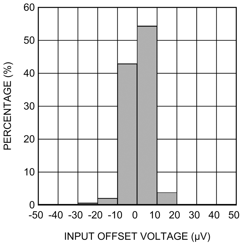 Figure 1. Offset Voltage Histogram
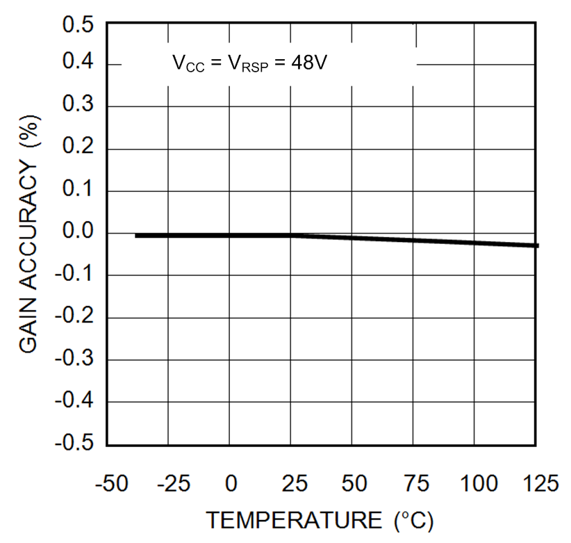 Figure 3. Typical Gain Accuracy vs Temperature
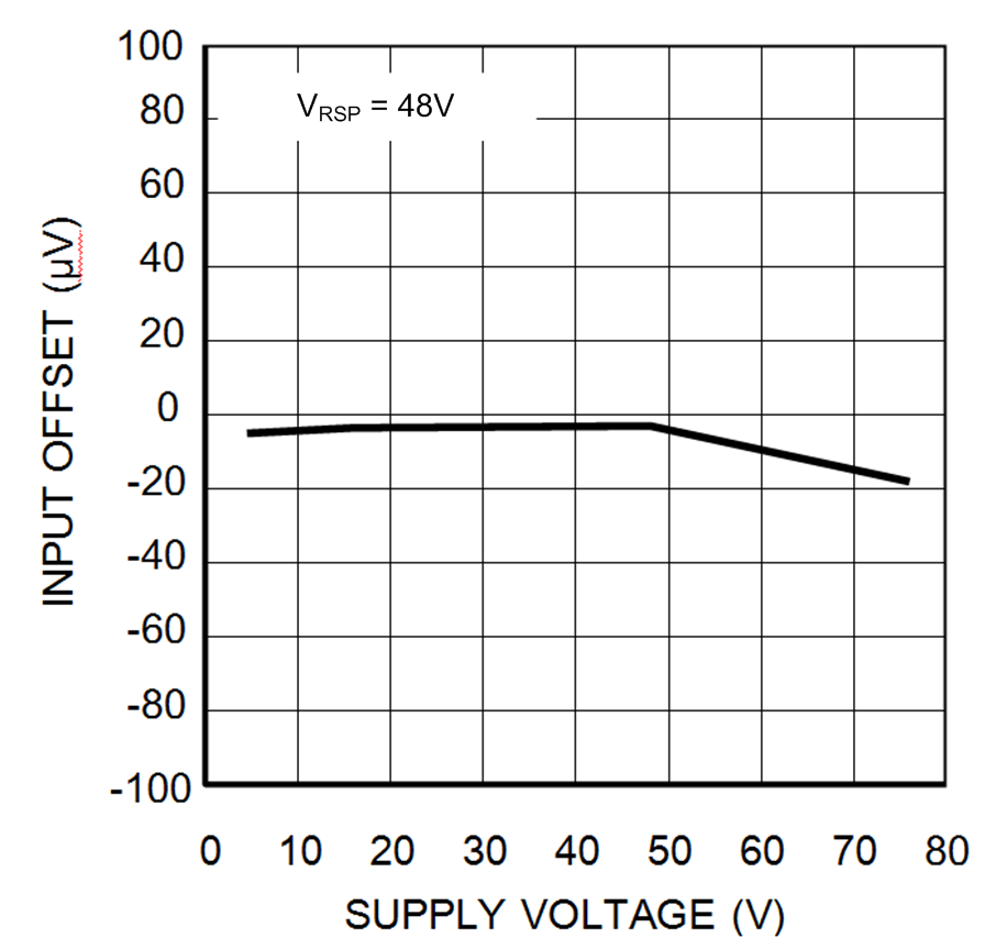 Figure 5. Typical Offset Voltage vs Supply Voltage
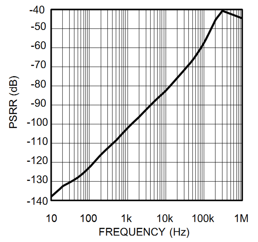 Figure 7. AC Power Supply Rejection Ratio vs Frequency
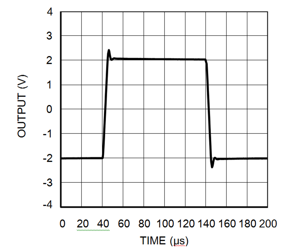 Figure 9. Large Signal Pulse Response
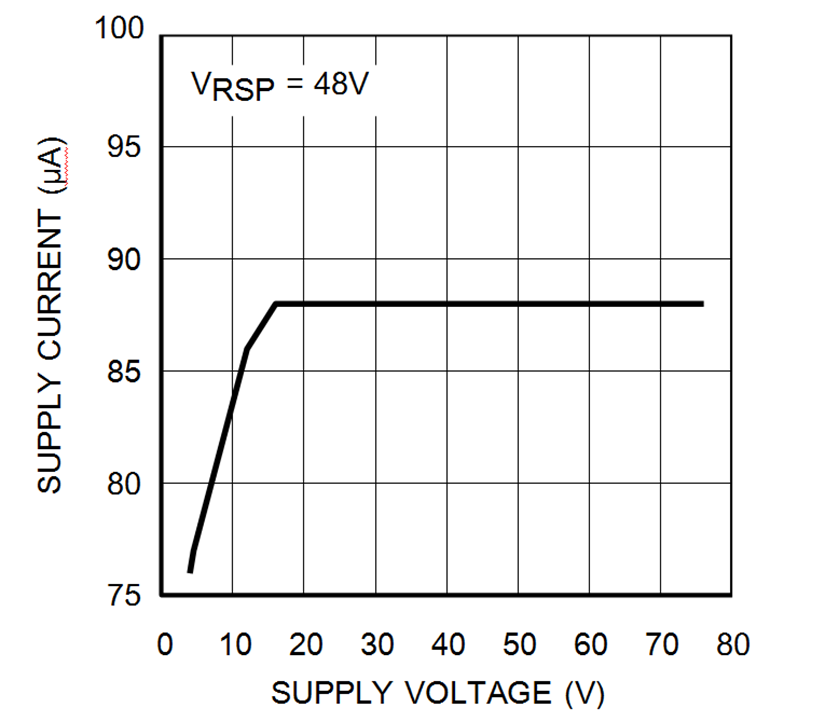 Figure 11. Supply Current vs Supply Voltage
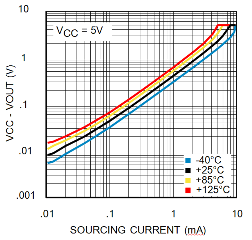 Figure 13. Saturated Output Sourcing Current at 4.5 V
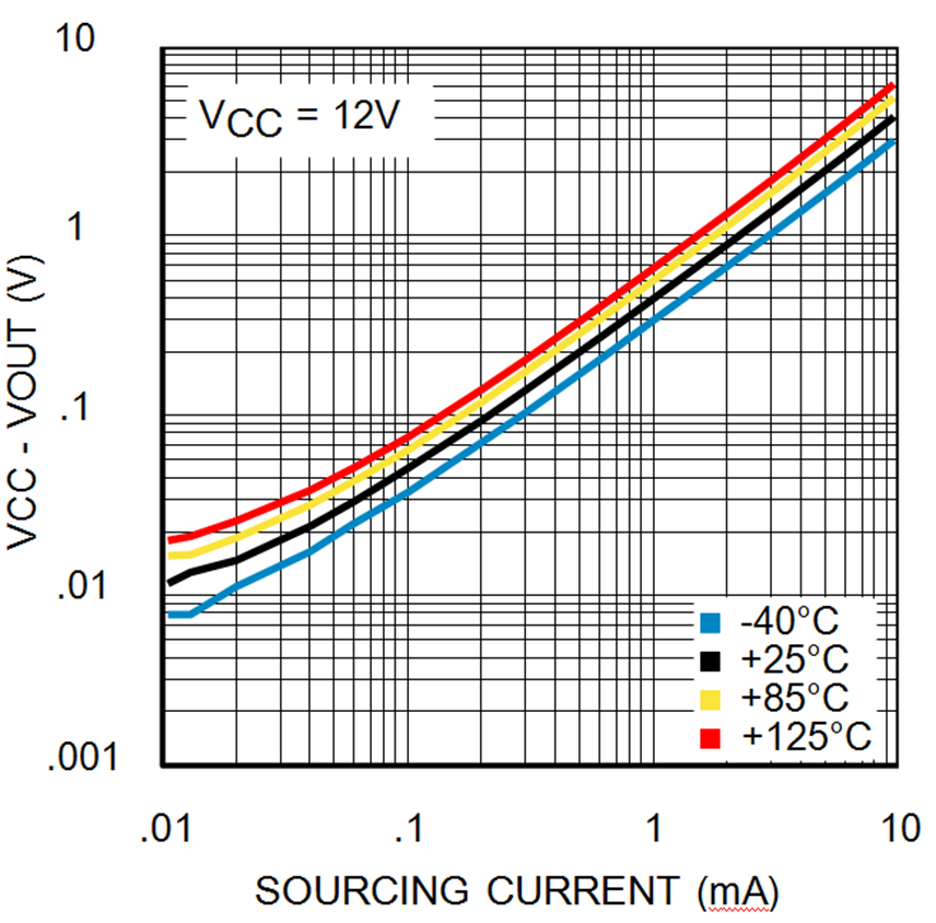 Figure 15. Saturated Output Sourcing Current at 12 V
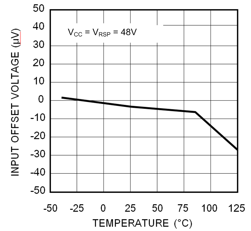 Figure 2. Typical Offset Voltage vs Temperature
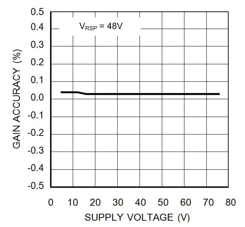 Figure 4. Typical Gain Accuracy vs Supply Voltage
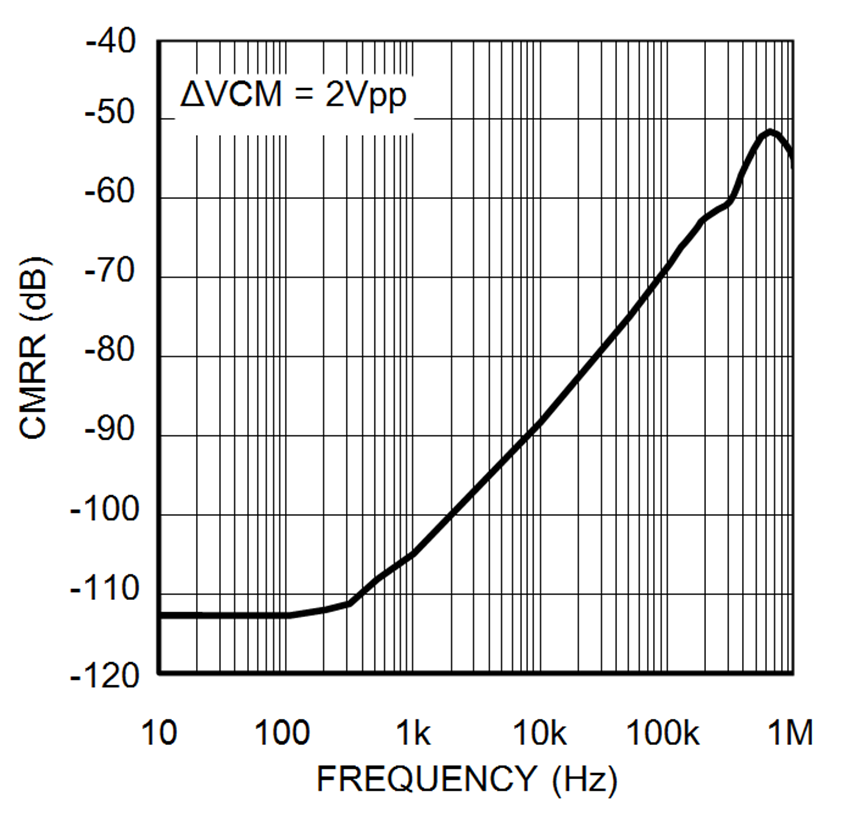 Figure 6. AC Common-Mode Rejection Ratio vs Frequency
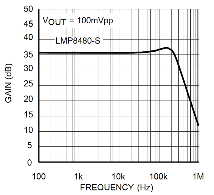 Figure 8. Small Signal Gain vs Frequency
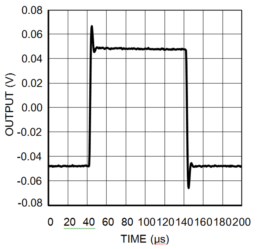 Figure 10. Small Signal Pulse Response
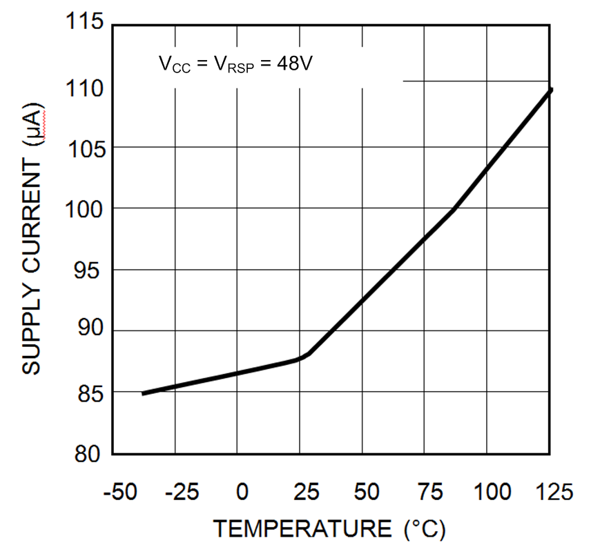 Figure 12. Supply Current vs Temperature
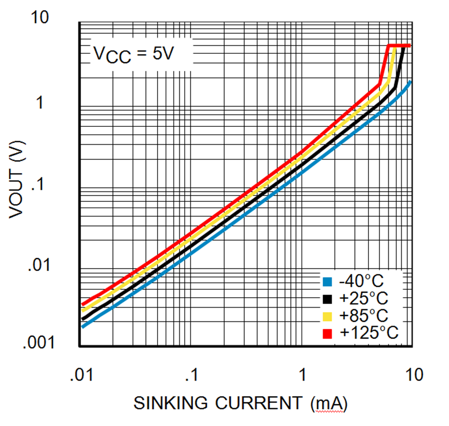 Figure 14. Saturated Output Sinking Current at 4.5 V
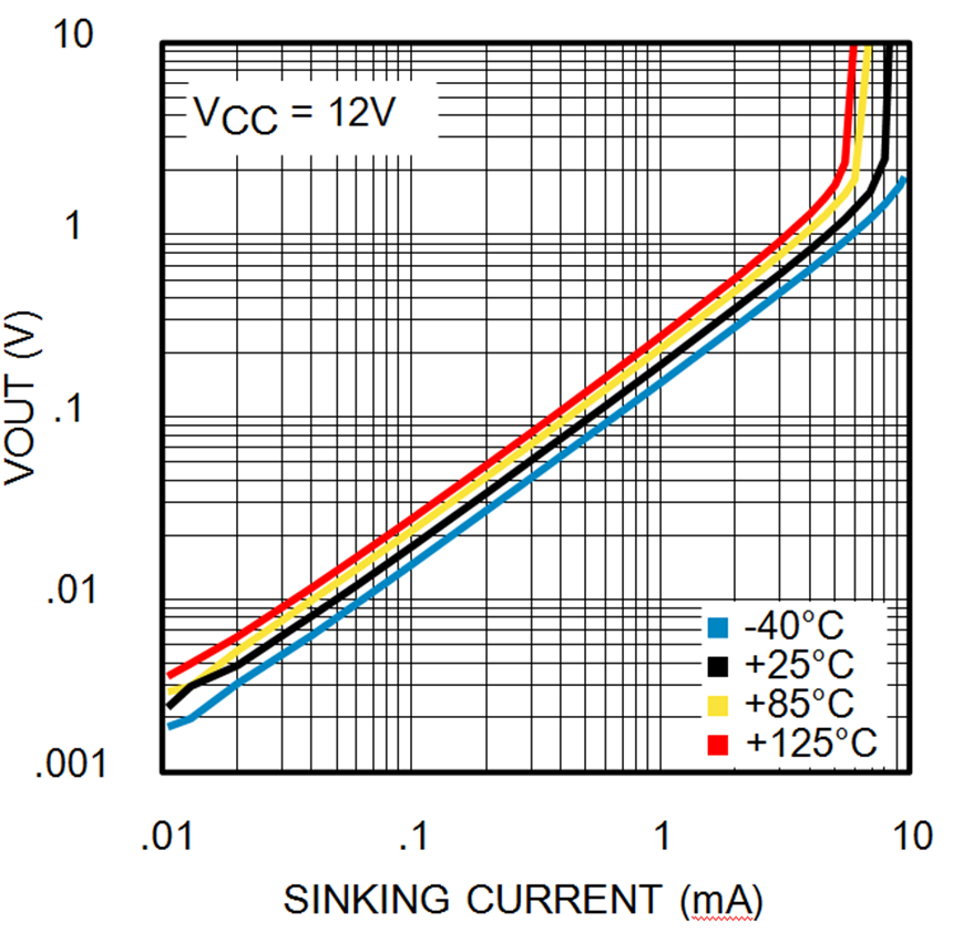 Figure 16. Saturated Output Current Sinking at 12 V