SNOSC63B February   2012  – December 2014 LMP8646

PRODUCTION DATA.  

  1. Features
  2. Applications
  3. Description
    1.     Device Images
      1.      Typical Application
  4. Revision History
  5. Pin Configuration and Functions
    1.     Pin Functions
  6. Specifications
    1. 6.1 Absolute Maximum Ratings
    2. 6.2 ESD Ratings
    3. 6.3 Recommended Operating Conditions
    4. 6.4 Thermal Information
    5. 6.5 Electrical Characteristics: 2.7 V
    6. 6.6 Electrical Characteristics: 5 V
    7. 6.7 Electrical Characteristics: 12 V
    8. 6.8 Typical Characteristics
  7. Detailed Description
    1. 7.1 Overview
    2. 7.2 Functional Block Diagram
    3. 7.3 Feature Description
      1. 7.3.1 Theory of Operation
        1. 7.3.1.1 Maximum Output Voltage, VOUT_MAX
          1. 7.3.1.1.1 Case 1: −2 V < VCM < 1.8 V, and VS > 2.7 V
          2. 7.3.1.1.2 Case 2: 1.8 V < VCM < VS, and VS > 3.3 V
          3. 7.3.1.1.3 Case 3: VCM > VS, and VS > 2.7 V
    4. 7.4 Device Functional Modes
      1. 7.4.1 Output Accuracy
      2. 7.4.2 Selection of the Sense Resistor, RSENSE
        1. 7.4.2.1 RSENSE Consideration for System Error
  8. Application and Implementation
    1. 8.1 Application Information
    2. 8.2 Typical Applications
      1. 8.2.1 Application #1: Current Limiter With a Capacitive Load
        1. 8.2.1.1 Design Requirements
        2. 8.2.1.2 Detailed Design Procedure
        3. 8.2.1.3 Application Curve
      2. 8.2.2 Application #2: Current Limiter With a Resistive Load
        1. 8.2.2.1 Design Requirements
        2. 8.2.2.2 Detailed Design Procedure
        3. 8.2.2.3 Application Curve
      3. 8.2.3 Application #3: Current Limiter With a Low-Dropout Regulator and Resistive Load
        1. 8.2.3.1 Design Requirements
        2. 8.2.3.2 Detailed Design Procedure
        3. 8.2.3.3 Application Curve
  9. Power Supply Recommendations
  10. 10Layout
    1. 10.1 Layout Guidelines
    2. 10.2 Layout Example
  11. 11Device and Documentation Support
    1. 11.1 Trademarks
    2. 11.2 Electrostatic Discharge Caution
    3. 11.3 Glossary
  12. 12Mechanical, Packaging, and Orderable Information

Package Options

Mechanical Data (Package|Pins)
Thermal pad, mechanical data (Package|Pins)
Orderable Information

RSENSE Consideration for System Error

The output accuracy described in the previous section talks about the error contributed just by the LMP8646. The system error, however, consists of the errors contributed by the LMP8646 as well as other external resistors such as RSENSE and RG. Let's rewrite the output accuracy equation for the system error assuming that RSENSE is non-ideal and RG is ideal. This equation can be seen as:
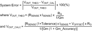
Equation 9. LMP8646 30123554.gif
System Error Example Assuming RSENSE is Non-ideal and RG is Ideal

Continuing from the previous output accuracy example, we can calculate for the system error assuming that RSENSE = 100 mOhm (with 1% tolerance), ISENSE = 1A, and RG = 10 kOhm. From the Electrical Characteristics Table, it is also known that VOFFSET = 1 mV and Gm_Accuracy = 2%.
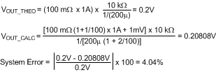
Equation 10. LMP8646 30123555.gif
System Error Example Assuming RSENSE is Non-ideal and RG is Ideal

Because an RSENSE tolerance will increase the system error, we recommend selecting an RSENSE resistor with low tolerance.