8.1 Absolute Maximum Ratings(1)(2)
|
MIN |
MAX |
UNIT |
| Supply voltage |
−0.3 |
6 |
V |
| Voltage at T_ON and TAO |
−0.3 |
6 |
V |
| Current at any pin |
|
5 |
mA |
| Storage temperature, Tstg |
-65 |
150 |
°C |
(1) Stresses beyond those listed under Absolute Maximum Ratings may cause permanent damage to the device. These are stress ratings only, which do not imply functional operation of the device at these or any other conditions beyond those indicated under Recommended Operating Conditions. Exposure to absolute-maximum-rated conditions for extended periods may affect device reliability.
(2) Soldering process must comply with Reflow Temperature Profile specifications. Refer to
www.ti.com/packaging.
8.2 ESD Ratings
|
VALUE |
UNIT |
| V(ESD) |
Electrostatic discharge |
Human-body model (HBM), per ANSI/ESDA/JEDEC JS-001(1) |
±2000 |
V |
| Charged-device model (CDM), per JEDEC specification JESD22-C101(2) |
±750 |
(1) JEDEC document JEP155 states that 500-V HBM allows safe manufacturing with a standard ESD control process.
(2) JEDEC document JEP157 states that 250-V CDM allows safe manufacturing with a standard ESD control process.
8.5 Electrical Characteristics
Limits apply for TA = TJ = TMIN to TMAX and VDD of 2.00V to 5.5V and VDD ≥ VTAO + 1V, unless otherwise noted.
| PARAMETER |
TEST CONDITIONS |
MIN |
TYP |
MAX |
UNIT |
| TEMPERATURE ACCURACY |
|
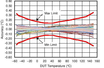
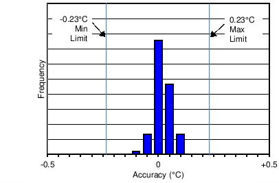
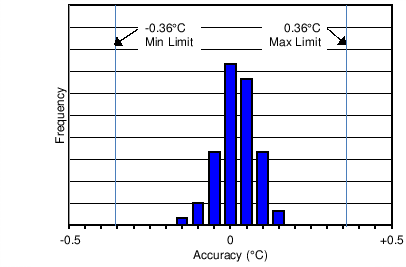
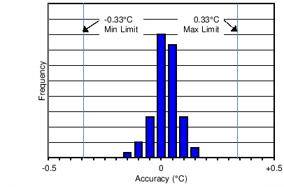
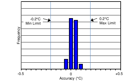
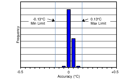
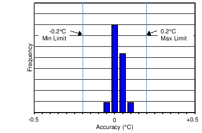
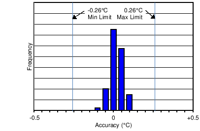
TAO accuracy
(These stated accuracy limits are with reference to the values in Electrical Characteristics Temperature Lookup Table (LUT), LMT70 temperature-to-voltage.)(1) |
TA = –55°C |
VDD = 2.7 V |
-0.33 |
|
0.33 |
°C |
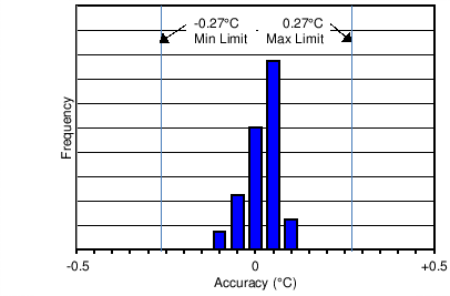
| TA = –40°C |
VDD = 2.7 V |
–0.27 |
|
0.27 |
| TA = –20°C |
VDD = 2.7 V |
–0.2 |
|
0.2 |
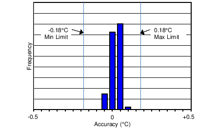
| TA = –10°C |
VDD = 2.7 V |
–0.18 |
|
0.18 |
| TA = 20°C to 42°C |
VDD = 2.7 V |
–0.13 |
±0.05 |
0.13 |
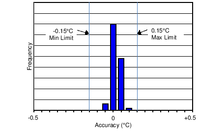
| TA = 50°C |
VDD = 2.7 V |
-0.15 |
|
0.15 |
| TA = 90°C |
VDD = 2.7 V |
–0.20 |
|
0.20 |
| TA = 110°C |
VDD = 2.7 V |
–0.23 |
|
0.23 |
| TA = 150°C |
VDD = 2.7 V |
–0.36 |
|
0.36 |
| ATC |
Accuracy temperature coefficient (note, uses end point calculations)(2) |
VDD = 2.7V |
-2.6 |
|
+2.6 |
m°C/°C |
| APSS |
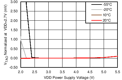
Accuracy power supply sensitivity (note uses end point calculations) |
–55°C ≤ TA ≤ 10°C |
VDD = VTAO + 1.1 V to 4.0 V |
–9 |
–2 |
8 |
m°C /V |
| 10°C ≤ TA ≤ 120°C |
VDD = 2.0 V to 4.0 V |
| 120°C ≤ TA ≤ 150°C |
VDD = 2.0 V to 4.0 V |
–15 |
|
8 |
|
VDD = 4 V to 5.5 V |
–30 |
–12 |
0 |
| VTAO |
Output Voltage |
TA = 30°C |
VDD = 2.7 V |
|
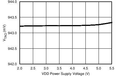
943.227 |
|
mV |
|
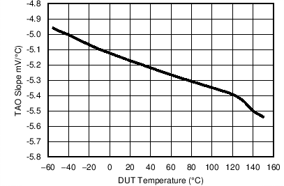
Sensor gain |
|
|
–5.194 |
|
mV/°C |
|
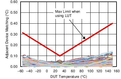
Matching of two adjacent parts in tape and reel for LMT70AYFQR, LMT70AYFQT only (see curve Figure 19 for specification at other temperatures)(3)(2) |
TA approximately 30°C |
VDD = 2.0 V to 3.6 V |
|
|
0.1 |
°C |
| TA = 30°C to 150°C |
|
|
2.5 |
m°C /°C |
| TA = 20°C to 30°C |
VDD = 2.0 V to 3.6 V |
-2.5 |
|
|
| TA = -55°C to 30°C |
VDD = 2.7 V to 3.6 V |
–2.5 |
|
|
|
Time stability(4) |
10k hours at 90°C |
–0.1 |
±0.01 |
0.1 |
°C |
| ANALOG OUTPUT |
|
Operating output voltage change with load current |
0 µA≤IL≤5 µA |
0 |
|
0.4 |
mV |
| -5 µA≤IL≤0 µA |
-0.4 |
|
0 |
mV |
| ROUT |
Output Resistance |
|
|
28 |
80 |
Ω |
|
TAO Off Leakage Current |
VTAO ≤ VDD – 0.6v, VT_ON=GND |
|
0.005 |
0.5 |
µA |
| VTAO ≥ 0.2V, VT_ON = GND |
-0.5 |
-0.005 |
|
|
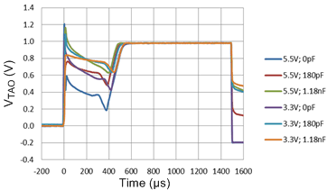
Output Load Capacitance |
|
|
|
1100 |
pF |
| POWER SUPPLY |
| VDO |
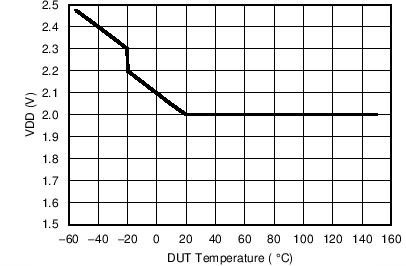
Dropout Voltage (VDD-VTAO)(5) |
–20°C ≤ TA ≤ 20°C |
1.0 |
|
|
V |
| –55°C ≤ TA ≤ –20°C |
1.1 |
|
|
|
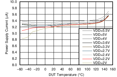
Power Supply Current |
|
|
9.2 |
12 |
µA |
|
Shutdown Current |
VDD ≤ 0.4V (-55°C to +110°C) |
|
|
50 |
nA |
| VDD ≤ 0.4V (+110°C to +150°C) |
|
|
350 |
nA |
| LOGIC INPUT |
|
T_ON Logic Low Input Threshold |
-55°C to +150°C |
0.5 |
0.33*VDD |
|
V |
|
T_ON Logic High Input Threshold |
-55°C to +150°C |
|
0.66*VDD |
VDD-0.5 |
V |
|
T_ON Input Current |
VT_ON = VDD |
|
0.15 |
1 |
µA |
| VT_ON = GND |
-1 |
-0.02 |
|
(1) Accuracy is defined as the error between the measured and reference output voltages, tabulated in the Conversion Table at the specified conditions of supply voltage and temperature (expressed in °C). These stated accuracy limits are with reference to the values in
Electrical Characteristics Temperature Lookup Table (LUT), see Accuracy Curve for other temperatures. Accuracy limits do not include load regulation or aging; they assume no DC load.
(2) The accuracy temperature coefficient specification is given to indicate part to part performance and does not correlate to the limits given in the curve
Figure 3.
(3) In order to meet the matching specification of the LMT70A, two units must be picked from adjacent positions from one tape and reel. If PCB rework is required, involving the LMT70A, then the pair of the LMT70A matched units must be replaced. Matching features (which include, without limitation, electrical matching characteristics of adjacent Components as they are delivered in original packaging from TI) are warranted solely to the extent that the purchaser can demonstrate to TI’s satisfaction that the particular Component(s) at issue were adjacent in original packaging as delivered by TI. Customers should be advised that the small size of these Components means they are not individually traceable at the unit level and it may be difficult to establish the original position of the Components once they have been removed from that original packaging as delivered by TI.
(4) Determined using accelerated operational life testing at 150°C junction temperature; not tested during production.
(5) Dropout voltage (VDO) is defined as the smallest possible differential voltage measured between VTAO and VDD that causes the temperature error to degrade by 0.02°C.
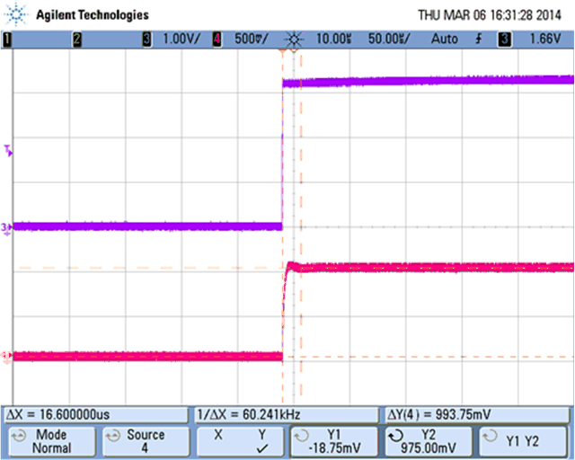
 Figure 1. Definition of tT_ON
 Figure 2. Definition of tPOWER
