SNVS610P December 2009 – April 2019 LMZ10504
PRODUCTION DATA.
- 1 Features
- 2 Applications
- 3 Description
- 4 Revision History
- 5 Pin Configuration and Functions
- 6 Specifications
- 7 Detailed Description
- 8 Application and Implementation
- 9 Power Supply Recommendations
- 10Layout
- 11Device and Documentation Support
- 12Mechanical, Packaging, and Orderable Information
Package Options
Mechanical Data (Package|Pins)
- NDW|7
Thermal pad, mechanical data (Package|Pins)
Orderable Information
5 Pin Configuration and Functions
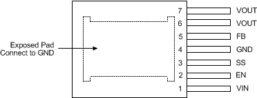
NDW Package
7-Lead TO-PMOD
Top View

Pin Functions
| PIN | TYPE | DESCRIPTION | |
|---|---|---|---|
| NAME | NO. | ||
| EN | 2 | Analog | Active-high enable input for the device. |
| Exposed Pad | — | Ground | Exposed pad is used as a thermal connection to remove heat from the device. Connect this pad to the PCB ground plane in order to reduce thermal resistance value. EP must also provide a direct electrical connection to the input and output capacitors ground terminals. Connect EP to pin 4. |
| FB | 5 | Analog | Feedback pin. This is the inverting input of the error amplifier used for sensing the output voltage. Keep the copper area of this node small. |
| GND | 4 | Ground | Power ground and signal ground. Provide a direct connection to the EP. Place the bottom feedback resistor as close as possible to GND and FB pin. |
| SS | 3 | Analog | Soft-start control pin. An internal 2-µA current source charges an external capacitor connected between SS and GND pins to set the output voltage ramp rate during start-up. The SS pin can also be used to configure the tracking feature. |
| VIN | 1 | Power | Power supply input. A low-ESR input capacitance should be located as close as possible to the VIN pin and exposed pad (EP). |
| VOUT | 6, 7 | Power | The output terminal of the internal inductor. Connect the output filter capacitor between VOUT pin and EP. |