-
LMZ20501 1-A Nano Module
- 1 Features
- 2 Applications
- 3 Description
- 4 Revision History
- 5 Pin Configuration and Functions
- 6 Specifications
- 7 Detailed Description
- 8 Application and Implementation
- 9 Power Supply Recommendations
- 10Layout
- 11Device and Documentation Support
- 12Mechanical, Packaging, and Orderable Information
- IMPORTANT NOTICE
Package Options
Refer to the PDF data sheet for device specific package drawings
Mechanical Data (Package|Pins)
- SIL|8
Thermal pad, mechanical data (Package|Pins)
Orderable Information
LMZ20501 1-A Nano Module
1 Features
- Integrated inductor
- Miniature 3.5-mm × 3.5-mm × 1.75-mm package
- 1-A maximum load current
- Input voltage range of 2.7 V to 5.5 V
- Adjustable output voltage range of 0.8 V to 3.6 V
- ± 1% feedback tolerance over temperature
- 2.4-µA (maximum) quiescent current in shutdown
- 3-MHz fixed PWM switching frequency
- –40°C to 125°C junction temperature range
- Power-good flag function
- Pin-selectable switching modes
- Internal compensation and soft start
- Current limit, thermal shutdown, and UVLO protection
- Create a custom design using the LMZ20501 with WEBENCH® Power Designer
2 Applications
3 Description
The LMZ20501 nano module regulator is an easy-to-use synchronous step-down DC/DC converter capable of driving up to 1 A of load from an input of up to 5.5 V, with exceptional efficiency and output accuracy in a very small solution size. The innovative package contains the regulator and inductor in a small 3.5 mm × 3.5 mm × 1.75 mm volume, thus saving board space and eliminating the time and expense of inductor selection. The LMZ20501 requires only five external components and has a pin-out designed for simple, optimum PCB layout. The device provides for an easy to use complete design with a minimum number of external components and the TI WEBENCH® design tool. TI's WEBENCH tool includes features such as external component calculation, electrical simulation, and WebTherm®. For soldering information, see SNOA401.
| PART NUMBER | PACKAGE(1) | BODY SIZE (NOM) |
|---|---|---|
| LMZ20501 | USIP (8) | 3.50 mm × 3.50 mm |
 Simplified Schematic
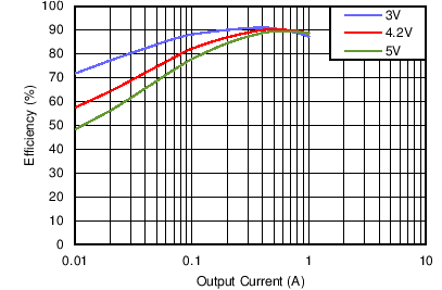
 Typical Efficiency for
VOUT = 1.8 V Auto Mode
Typical Efficiency for
VOUT = 1.8 V Auto Mode4 Revision History
Changes from Revision D (August 2018) to Revision E (September 2021)
- Updated the numbering format for tables, figures, and cross-references throughout the document. Go
- Updated Figure 7-3 titleGo
Changes from Revision C (April 2015) to Revision D (August 2018)
- Deleted Simple Switcher branding; added links for WEBENCH Go
5 Pin Configuration and Functions
 Figure 5-1 8-PinsUSIP Package (SIL)(Top View)
| PIN | TYPE(1) | DESCRIPTION | |
|---|---|---|---|
| NUMBER | NAME | ||
| 1 | PG | O | Power-good flag; open drain. Connect to logic supply through a resistor. High = power good; low = power bad. If not used, leave unconnected. |
| 2 | EN | I | Enable input. High = On, Low = Off. A valid input voltage, on pin 8, must be present before EN is asserted. Do not float. |
| 3 | MODE | I | Mode selection input. High = forced PWM. Low = AUTO mode with PFM at light load. Do not float. |
| 4 | FB | I | Feedback input to controller. Connect to output through feedback divider. |
| 5 | VOUT | P | Regulated output voltage. Connect to COUT. |
| 6 | GND | G | Ground for all circuitry. Reference point for all voltages |
| 7 | NC | — | This pin must be left floating. Do not connect to ground or any other node. |
| 8 | VIN | P | Input supply to regulator. Connect to input capacitor(s) as close as possible to the VIN pin and GND pin of the module. |
| EP | EP | G | Ground and heat-sink connection. See Section 10.1 for more information. |
6 Specifications
6.1 Absolute Maximum Ratings
| MIN | MAX | UNIT | ||
|---|---|---|---|---|
| VIN to GND | –0.2 | 6 | V | |
| EN, MODE, FB, PG, to GND(2) | –0.2 | VIN+0.2 | ||
| VOUT to GND(2) | –0.2 | VIN+0.2 | ||
| Junction temperature | 150 | °C | ||
| Peak soldering reflow temperature for Pb(3) | 240 | °C | ||
| Peak soldering reflow temperature for No-Pb(3) | 260 | |||
| Storage temperature range | –65 | 150 | °C | |