SNOSAI6J September   2005  – August 2016 LPV7215

PRODUCTION DATA.  

  1. Features
  2. Applications
  3. Description
  4. Revision History
  5. Pin Configuration and Functions
  6. Specifications
    1. 6.1 Absolute Maximum Ratings
    2. 6.2 ESD Ratings
    3. 6.3 Recommended Operating Conditions
    4. 6.4 Thermal Information
    5. 6.5 Electrical Characteristics: 1.8 V
    6. 6.6 Electrical Characteristics: 2.7 V
    7. 6.7 Electrical Characteristics: 5 V
    8. 6.8 Typical Characteristics
  7. Detailed Description
    1. 7.1 Overview
    2. 7.2 Functional Block Diagram
    3. 7.3 Feature Description
      1. 7.3.1 Input Stage
      2. 7.3.2 Output Stage
      3. 7.3.3 Output Current
      4. 7.3.4 Response Time
    4. 7.4 Device Functional Modes
      1. 7.4.1 Capacitive and Resistive Loads
      2. 7.4.2 Noise
      3. 7.4.3 Hysteresis
      4. 7.4.4 Inverting Comparator With Hysteresis
      5. 7.4.5 Noninverting Comparator With Hysteresis
      6. 7.4.6 Zero Crossing Detector
      7. 7.4.7 Threshold Detector
  8. Application and Implementation
    1. 8.1 Application Information
    2. 8.2 Typical Applications
      1. 8.2.1 Square Wave Generator
        1. 8.2.1.1 Design Requirements
        2. 8.2.1.2 Detailed Design Procedure
        3. 8.2.1.3 Application Curves
      2. 8.2.2 Window Detector
      3. 8.2.3 Crystal Oscillator
      4. 8.2.4 IR Receiver
  9. Power Supply Recommendations
  10. 10Layout
    1. 10.1 Layout Guidelines
    2. 10.2 Layout Example
  11. 11Device and Documentation Support
    1. 11.1 Device Support
      1. 11.1.1 Development Support
      2. 11.1.2 Documentation Support
        1. 11.1.2.1 Related Documentation
    2. 11.2 Receiving Notification of Documentation Updates
    3. 11.3 Community Resources
    4. 11.4 Trademarks
    5. 11.5 Electrostatic Discharge Caution
    6. 11.6 Glossary
  12. 12Mechanical, Packaging, and Orderable Information

Package Options

Mechanical Data (Package|Pins)
Thermal pad, mechanical data (Package|Pins)
Orderable Information

10 Layout

10.1 Layout Guidelines

Proper grounding and the use of a ground plane help ensure the specified performance of the LPV7215. Minimizing trace lengths, reducing unwanted parasitic capacitance and using surface-mount components also helps.

10.2 Layout Example
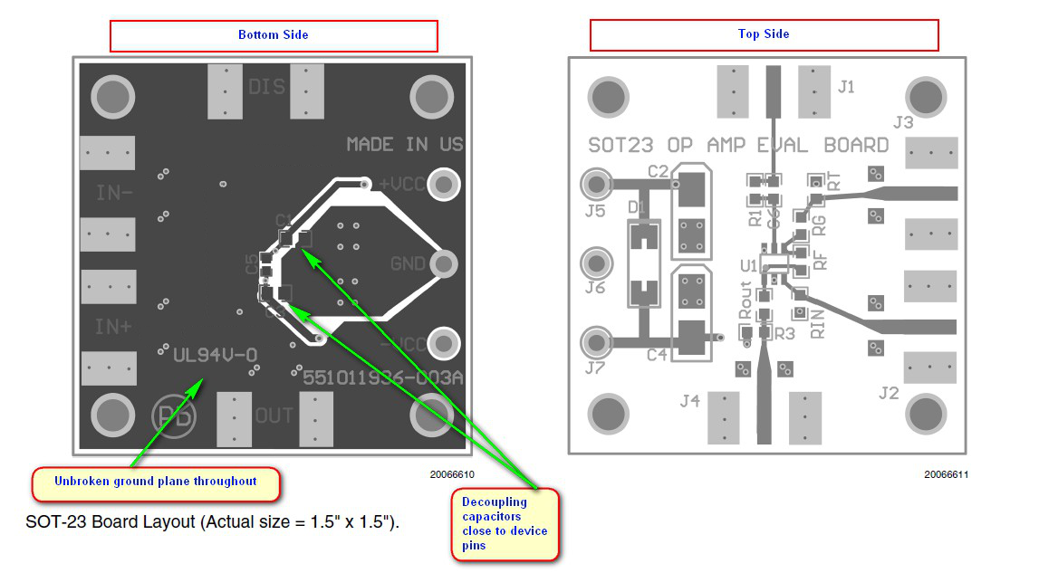
LPV7215 layout_images_SNOS458.png Figure 44. LPV7215 Layout Example