-
OPAx192 36-V, Precision, Rail-to-Rail Input/Output, Low Offset Voltage, Low Input Bias Current Op Amp with e-trim
- 1 Features
- 2 Applications
- 3 Description
- 4 Revision History
- 5 Pin Configuration and Functions
-
6 Specifications
- 6.1 Absolute Maximum Ratings
- 6.2 ESD Ratings
- 6.3 Recommended Operating Conditions
- 6.4 Thermal Information: OPA192
- 6.5 Thermal Information: OPA2192
- 6.6 Thermal Information: OPA4192
- 6.7 Electrical Characteristics: VS = ±4 V to ±18 V (VS = +8 V to +36 V)
- 6.8 Electrical Characteristics: VS = ±2.25 V to ±4 V (VS = +4.5 V to +8 V)
- 6.9 Typical Characteristics
- 6.10 Typical Characteristics
- 7 Parameter Measurement Information
- 8 Detailed Description
- 9 Application and Implementation
- 10Power-Supply Recommendations
- 11Layout
- 12Device and Documentation Support
- 13Mechanical, Packaging, and Orderable Information
- IMPORTANT NOTICE
Package Options
Mechanical Data (Package|Pins)
Thermal pad, mechanical data (Package|Pins)
Orderable Information
OPAx192 36-V, Precision, Rail-to-Rail Input/Output, Low Offset Voltage, Low Input Bias Current Op Amp with e-trim
1 Features
- Low Offset Voltage: ±5 µV
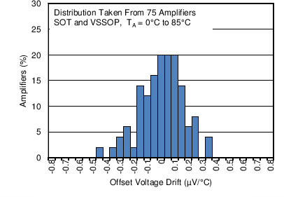
- Low Offset Voltage Drift: ±0.2 µV/°C
- Low Noise: 5.5 nV/√Hz at 1 kHz
- High Common-Mode Rejection: 140 dB
- Low Bias Current: ±5 pA
- Rail-to-Rail Input and Output
- Wide Bandwidth: 10 MHz GBW
- High Slew Rate: 20 V/µs
- Low Quiescent Current: 1 mA per Amplifier
- Wide Supply: ±2.25 V to ±18 V, 4.5 V to 36 V
- EMI/RFI Filtered Inputs
- Differential Input Voltage Range to Supply Rail
- High Capacitive Load Drive Capability: 1 nF
-
Industry Standard Packages:
- Single in SOIC-8, SOT-23-5, and VSSOP-8
- Dual in SOIC-8 and VSSOP-8
- Quad in SOIC-14 and TSSOP-14
2 Applications
- Multiplexed Data-Acquisition Systems
- Test and Measurement Equipment
- High-Resolution ADC Driver Amplifiers
- SAR ADC Reference Buffers
- Programmable Logic Controllers
- High-Side and Low-Side Current Sensing
- High Precision Comparator
3 Description
The OPAx192 family (OPA192, OPA2192, and OPA4192) is a new generation of 36-V, e-trim operational amplifiers.
These devices offer outstanding dc precision and ac performance, including rail-to-rail input/output, low offset (±5 µV, typ), low offset drift (±0.2 µV/°C, typ), and 10-MHz bandwidth.
Unique features such as differential input-voltage range to the supply rail, high output current (±65 mA), high capacitive load drive of up to 1 nF, and high slew rate (20 V/µs) make the OPA192 a robust, high-performance operational amplifier for high-voltage industrial applications.
The OPA192 family of op amps is available in standard packages and is specified from –40°C to +125°C.
Device Information(1)
- For all available packages, see the package option addendum at the end of the data sheet.
OPA192 in a High-Voltage, Multiplexed, Data-Acquisition System

4 Revision History
Changes from D Revision (September 2015) to E Revision
- Changed PW package from product preview to production dataGo
- Added PW package to test condition for input offset voltage driftGo
- Added PW package to test condition for input offset voltage driftGo
- Added PW package condition to Figure 8 Go
- Added PW package condition to Figure 10 Go
- Added PW package condition to Figure 52 Go
- Changed Figure 70 to fix typosGo
Changes from C Revision (March 2015) to D Revision
- Changed device status to Production Data; OPA4192 released to Production Go
- Deleted footnote 2 from Device Information table Go
- Deleted footnote 2 from Pin Configuration and Functions sectionGo
- Changed ESD Ratings table: added correct OPA4192 CDM specifications Go
- Added Frequency Response, Crosstalk parameter to Electrical Characteristics: VS = ±4 V to ±18 V table Go
- Added Frequency Response, Crosstalk parameter to Electrical Characteristics: VS = ±2.25 V to ±4 V table Go
- Changed Typical Characteristics to current standards (split curves and table of graphs into separate sections to be SDS compliant) Go
- Added Crosstalk vs Frequency row to Table 1 Go
- Added Figure 48 Go
Changes from B Revision (March 2014) to C Revision
- Added CDM row for OPA2192, OPA4192 in ESD Ratings tableGo
- Changed input offset voltage values for VCM ≥ (V+) – 1.5 V test conditionGo
- Changed Input offset voltage parameter typical specs for VCM = (V+) – 1.5 V test conditions Go
- Changed test conditions for dVOS/dT parameterGo
- Changed input offset voltage max values and test conditions for VCM = (V+) – 3 V test conditionGo
- Changed input offset voltage values and test conditions for VCM = (V+) – 1.5 V test conditionGo
- Changed Input offset voltage parameter typical specs for VCM = (V+) – 1.5 V test conditionsGo
- Changed test conditions for dVOS/dT parameter Go
- Added text to last bullet of Layout Guidelines sectionGo
Changes from A Revision (January 2014) to B Revision
- Added ESD Ratings and Recommended Operating Conditions tables, and Parameter Measurement Information, Application and Implementation, Power-Supply Recommendations, and Device and Documentation Support sections, and moved existing sectionsGo
- Changed all OPA192 and OPA2192 packages to production data.Go
- Changed package names to latest standard; changed all MSOP to VSSOP, SO to SOIC, and SOT23 to SOT Go
- Deleted DCK package pin configurationGo
- Added thermal information for OPA192 DBV and DGK packagesGo
- Added OPA2192 and OPA4192 Thermal Information tables Go
- Added rows with additional test conditions to input offset voltage parameterGo
- Changed Input offset voltage drift parameter Go
- Changed CMRR test conditions Go
- Added rows with additional test conditions to input offset voltage parameterGo
- Changed Input offset voltage drift parameterGo
- Changed PSSR parameter Go
- Changed CMRR test conditions Go
- Added Output sectionGo
- Added typical characteristic curves to Table 1 Go
- Added TA = 25°C to Typical Characteristics condition line Go
- Added nine new histogram plots from Figure 2 to Figure 10Go
- Changed Figure 11 to show more unitsGo
- Changed Figure 19 Go
- Added text to Application Information sectionGo
- Changed text in Layout Guidelines sectionGo
Changes from * Revision (December 2013) to A Revision
- Changed first paragraph of 16-Bit Precision Multiplexed Data-Acquisition System sectionGo
- Changed Figure 66 and titleGo
- Changed TIDU181 reference design titleGo
5 Pin Configuration and Functions
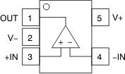
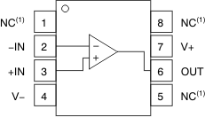
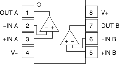
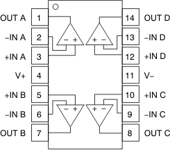
Pin Functions: OPA192
| PIN | I/O | DESCRIPTION | ||
|---|---|---|---|---|
| NAME | OPA192 | |||
| D (SOIC), DGK (VSSOP) |
DBV (SOT) | |||
| +IN | 3 | 3 | I | Noninverting input |
| –IN | 2 | 4 | I | Inverting input |
| NC | 1, 5, 8 | — | — | No internal connection (can be left floating) |
| OUT | 6 | 1 | O | Output |
| V+ | 7 | 5 | — | Positive (highest) power supply |
| V– | 4 | 2 | — | Negative (lowest) power supply |
Pin Functions: OPA2192 and OPA4192
| PIN | I/O | DESCRIPTION | ||
|---|---|---|---|---|
| NAME | OPA2192 | OPA4192 | ||
| D (SOIC), DGK (VSSOP) |
D (SOIC), PW (TSSOP) |
|||
| +IN A | 3 | 3 | I | Noninverting input, channel A |
| +IN B | 5 | 5 | I | Noninverting input, channel B |
| +IN C | — | 10 | I | Noninverting input, channel C |
| +IN D | — | 12 | I | Noninverting input, channel D |
| –IN A | 2 | 2 | I | Inverting input, channel A |
| –IN B | 6 | 6 | I | Inverting input, channel B |
| –IN C | — | 9 | I | Inverting input,,channel C |
| –IN D | — | 13 | I | Inverting input, channel D |
| OUT A | 1 | 1 | O | Output, channel A |
| OUT B | 7 | 7 | O | Output, channel B |
| OUT C | — | 8 | O | Output, channel C |
| OUT D | — | 14 | O | Output, channel D |
| V+ | 8 | 4 | — | Positive (highest) power supply |
| V– | 4 | 11 | — | Negative (lowest) power supply |
6 Specifications
6.1 Absolute Maximum Ratings(1)
over operating free-air temperature range (unless otherwise noted)| MIN | MAX | UNIT | |||
|---|---|---|---|---|---|
| Supply voltage, VS = (V+) – (V–) | ±20 (40, single supply) |
V | |||
| Signal input pins | Voltage | Common-mode | (V–) – 0.5 | (V+) + 0.5 | V |
| Differential | (V+) – (V–) + 0.2 | ||||
| Current | ±10 | mA | |||
| Output short circuit(2) | Continuous | ||||
| Temperature | Operating range | –55 | 150 | °C | |
| Junction | 150 | ||||
| Storage, Tstg | –65 | 150 | |||
6.2 ESD Ratings
| VALUE | UNIT | |||
|---|---|---|---|---|
| V(ESD) | Electrostatic discharge | Human-body model (HBM), per ANSI/ESDA/JEDEC JS-001(1) | ±4000 | V |
| OPA192 | ||||
| V(ESD) | Electrostatic discharge | Charged-device model (CDM), per JEDEC specification JESD22-C101(2) | ±1000 | V |
| OPA2192 | ||||
| V(ESD) | Electrostatic discharge | Charged-device model (CDM), per JEDEC specification JESD22-C101(2) | ±750 | V |
| OPA4192 | ||||
| V(ESD) | Electrostatic discharge | Charged-device model (CDM), per JEDEC specification JESD22-C101(2) | ±500 | V |
6.3 Recommended Operating Conditions
over operating free-air temperature range (unless otherwise noted)| MIN | NOM | MAX | UNIT | ||
|---|---|---|---|---|---|
| Supply voltage, VS = (V+) – (V–) | 4.5 (±2.25) | 36 (±18) | V | ||
| Specified temperature | –40 | +125 | °C | ||
6.4 Thermal Information: OPA192
| THERMAL METRIC(1) | OPA192 | UNIT | |||
|---|---|---|---|---|---|
| D (SOIC) | DBV (SOT) | DGK (VSSOP) | |||
| 8 PINS | 5 PINS | 8 PINS | |||
| RθJA | Junction-to-ambient thermal resistance | 115.8 | 158.8 | 180.4 | °C/W |
| RθJC(top) | Junction-to-case(top) thermal resistance | 60.1 | 60.7 | 67.9 | °C/W |
| RθJB | Junction-to-board thermal resistance | 56.4 | 44.8 | 102.1 | °C/W |
| ψJT | Junction-to-top characterization parameter | 12.8 | 1.6 | 10.4 | °C/W |
| ψJB | Junction-to-board characterization parameter | 55.9 | 4.2 | 100.3 | °C/W |
| RθJC(bot) | Junction-to-case(bottom) thermal resistance | N/A | N/A | N/A | °C/W |
6.5 Thermal Information: OPA2192
| THERMAL METRIC(1) | OPA2192 | UNIT | ||
|---|---|---|---|---|
| D (SOIC) | DGK (VSSOP) | |||
| 8 PINS | 8 PINS | |||
| RθJA | Junction-to-ambient thermal resistance | 107.9 | 158 | °C/W |
| RθJC(top) | Junction-to-case(top) thermal resistance | 53.9 | 48.6 | °C/W |
| RθJB | Junction-to-board thermal resistance | 48.9 | 78.7 | °C/W |
| ψJT | Junction-to-top characterization parameter | 6.6 | 3.9 | °C/W |
| ψJB | Junction-to-board characterization parameter | 48.3 | 77.3 | °C/W |
| RθJC(bot) | Junction-to-case(bottom) thermal resistance | N/A | N/A | °C/W |
6.6 Thermal Information: OPA4192
| THERMAL METRIC(1) | OPA4192 | UNIT | ||
|---|---|---|---|---|
| D (SOIC) | PW (TSSOP) | |||
| 14 PINS | 14 PINS | |||
| RθJA | Junction-to-ambient thermal resistance | 86.4 | 92.6 | °C/W |
| RθJC(top) | Junction-to-case(top) thermal resistance | 46.3 | 27.5 | °C/W |
| RθJB | Junction-to-board thermal resistance | 41.0 | 33.6 | °C/W |
| ψJT | Junction-to-top characterization parameter | 11.3 | 1.9 | °C/W |
| ψJB | Junction-to-board characterization parameter | 40.7 | 33.1 | °C/W |
| RθJC(bot) | Junction-to-case(bottom) thermal resistance | N/A | N/A | °C/W |
6.7 Electrical Characteristics: VS = ±4 V to ±18 V (VS = +8 V to +36 V)
At TA = +25°C, VCM = VOUT = VS / 2, and RLOAD = 10 kΩ connected to VS / 2, unless otherwise noted.| PARAMETER | TEST CONDITIONS | MIN | TYP | MAX | UNIT | ||
|---|---|---|---|---|---|---|---|
| OFFSET VOLTAGE | |||||||
| VOS | Input offset voltage | ±5 | ±25 | µV | |||
| TA = 0°C to 85°C | ±8 | ±50 | |||||
| TA = –40°C to +125°C | ±10 | ±75 | |||||
| VCM = (V+) – 1.5 V | ±10 | ±40 | |||||
| TA = 0°C to 85°C | ±25 | ±150 | |||||
| TA = –40°C to +125°C | ±50 | ±250 | |||||
| dVOS/dT | Input offset voltage drift | D packages only | TA = 0°C to 85°C | ±0.1 | ±0.5 | µV/°C | |
| TA = –40°C to +125°C | ±0.15 | ±0.8 | |||||
| DBV, DGK, and PW packages only | TA = 0°C to 85°C | ±0.1 | ±0.8 | ||||
| TA = –40°C to +125°C | ±0.2 | ±1.0 | |||||
| PSRR | Power-supply rejection ratio | TA = –40°C to +125°C | ±0.3 | ±1.0 | µV/V | ||
| INPUT BIAS CURRENT | |||||||
| IB | Input bias current | ±5 | ±20 | pA | |||
| TA = –40°C to +125°C | ±5 | nA | |||||
| IOS | Input offset current | ±2 | ±20 | pA | |||
| TA = –40°C to +125°C | ±2 | nA | |||||
| NOISE | |||||||
| En | Input voltage noise | (V–) – 0.1 V < VCM < (V+) – 3 V | f = 0.1 Hz to 10 Hz | 1.30 | µVPP | ||
| (V+) – 1.5 V < VCM < (V+) + 0.1 V | f = 0.1 Hz to 10 Hz | 4 | |||||
| en | Input voltage noise density | (V–) – 0.1 V < VCM < (V+) – 3 V | f = 100 Hz | 10.5 | nV/√Hz | ||
| f = 1 kHz | 5.5 | ||||||
| (V+) – 1.5 V < VCM < (V+) + 0.1 V | f = 100 Hz | 32 | |||||
| f = 1 kHz | 12.5 | ||||||
| NOISE (continued) | |||||||
| in | Input current noise density | f = 1 kHz | 1.5 | fA/√Hz | |||
| INPUT VOLTAGE | |||||||
| VCM | Common-mode voltage range | (V–) – 0.1 | (V+) + 0.1 | V | |||
| CMRR | Common-mode rejection ratio | (V–) – 0.1 V < VCM < (V+) – 3 V | 120 | 140 | dB | ||
| TA = –40°C to +125°C | 114 | 126 | |||||
| (V+) – 1.5 V < VCM < (V+) | 100 | 120 | |||||
| TA = –40°C to +125°C | 86 | 100 | |||||
| (V+) – 3 V < VCM < (V+) – 1.5 V | See Typical Characteristics | ||||||
| INPUT IMPEDANCE | |||||||
| ZID | Differential | 100 || 1.6 | MΩ || pF | ||||
| ZIC | Common-mode | 1 || 6.4 | 1013Ω || pF | ||||
| OPEN-LOOP GAIN | |||||||
| AOL | Open-loop voltage gain | (V–) + 0.6 V < VO < (V+) – 0.6 V, RLOAD = 2 kΩ | 120 | 134 | dB | ||
| TA = –40°C to +125°C | 114 | 126 | |||||
| (V–) + 0.3 V < VO < (V+) – 0.3 V, RLOAD = 10 kΩ | 126 | 140 | |||||
| TA = –40°C to +125°C | 120 | 134 | |||||
| FREQUENCY RESPONSE | |||||||
| GBW | Unity gain bandwidth | 10 | MHz | ||||
| SR | Slew rate | G = 1, 10-V step | 20 | V/µs | |||
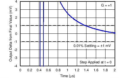
| ts | Settling time | To 0.01% | V S = ±18 V, G = 1, 10-V step | 1.4 | µs | ||
| V S = ±18 V, G = 1, 5-V step | 0.9 | ||||||
| To 0.001% | V S = ±18 V, G = 1, 10-V step | 2.1 | |||||
| V S = ±18 V, G = 1, 5-V step | 1.8 | ||||||
| tOR | Overload recovery time | VIN × G = VS | 200 | ns | |||
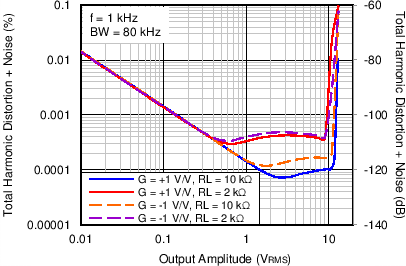
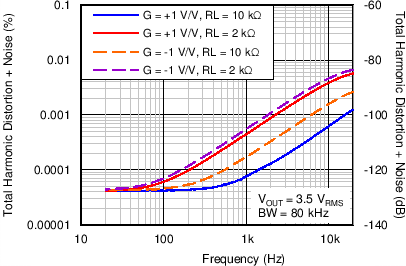
| THD+N | Total harmonic distortion + noise | G = 1, f = 1 kHz, VO = 3.5 VRMS | 0.00008% | ||||
| Crosstalk | OPA2192 and OPA4192, at dc | 150 | dB | ||||
| OPA2192 and OPA4192, f = 100 kHz | 130 | ||||||
| OUTPUT | |||||||
| VO | Voltage output swing from rail | Positive rail | No load | 5 | 15 | mV | |
| RLOAD = 10 kΩ | 95 | 110 | |||||
| RLOAD = 2 kΩ | 430 | 500 | |||||
| Negative rail | No load | 5 | 15 | ||||
| RLOAD = 10 kΩ | 95 | 110 | |||||
| RLOAD = 2 kΩ | 430 | 500 | |||||
| ISC | Short-circuit current | ±65 | mA | ||||
| CLOAD | Capacitive load drive | See Typical Characteristics | |||||
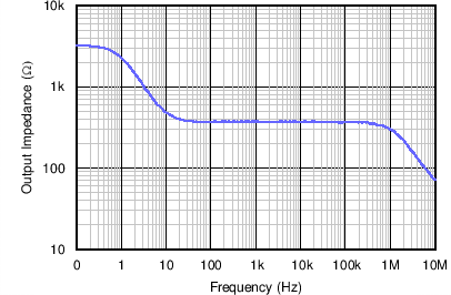
| ZO | Open-loop output impedance | f = 1 MHz, IO = 0 A, see Figure 31 | 375 | Ω | |||
| POWER SUPPLY | |||||||
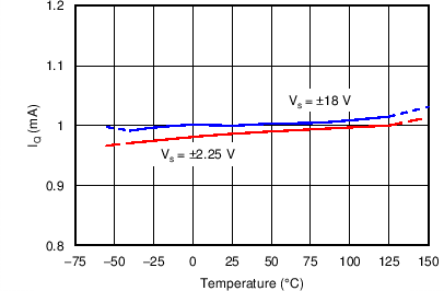
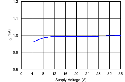
| IQ | Quiescent current per amplifier | IO = 0 A | 1 | 1.2 | mA | ||
| TA = –40°C to +125°C, IO = 0 A | 1.5 | ||||||
| TEMPERATURE | |||||||
| Thermal protection(1) | 140 | °C | |||||
6.8 Electrical Characteristics: VS = ±2.25 V to ±4 V (VS = +4.5 V to +8 V)
At TA = +25°C, VCM = VOUT = VS / 2, and RLOAD = 10 kΩ connected to VS / 2, unless otherwise noted.| PARAMETER | TEST CONDITIONS | MIN | TYP | MAX | UNIT | ||
|---|---|---|---|---|---|---|---|
| OFFSET VOLTAGE | |||||||
| VOS | Input offset voltage | VCM = (V+) – 3 V | ±5 | ±25 | µV | ||
| TA = 0°C to 85°C | ±8 | ±50 | |||||
| TA = –40°C to +125°C | ±10 | ±75 | |||||
| (V+) – 3.5 V < VCM < (V+) – 1.5 V | See Common-Mode Voltage Range section | ||||||
| VCM = (V+) – 1.5 V | ±10 | ±40 | µV | ||||
| TA = 0°C to 85°C | ±25 | ±150 | |||||
| TA = –40°C to +125°C | ±50 | ±250 | |||||
| dVOS/dT | Input offset voltage drift | VCM = (V+) – 3 V, D packages only |
TA = 0°C to 85°C | ±0.1 | ±0.5 | µV/°C | |
| TA = –40°C to +125°C | ±0.15 | ±0.8 | |||||
| VCM = (V+) – 3 V, DBV, DGK, and PW packages only |
TA = 0°C to 85°C | ±0.1 | ±0.8 | ||||
| TA = –40°C to +125°C | ±0.2 | ±1.1 | |||||
| VCM = (V+) – 1.5 V, TA = –40°C to +125°C | ±0.5 | ±3 | |||||
| PSRR | Power-supply rejection ratio | TA = –40°C to +125°C, VCM = VS / 2 – 0.75 V | ±1 | µV/V | |||
| INPUT BIAS CURRENT | |||||||
| IB | Input bias current | ±5 | ±20 | pA | |||
| TA = –40°C to +125°C | ±5 | nA | |||||
| IOS | Input offset current | ±2 | ±20 | pA | |||
| TA = –40°C to +125°C | ±2 | nA | |||||
| NOISE | |||||||
| En | Input voltage noise | (V–) – 0.1 V < VCM < (V+) – 3 V, f = 0.1 Hz to 10 Hz | 1.30 | µVPP | |||
| (V+) – 1.5 V < VCM < (V+) + 0.1 V, f = 0.1 Hz to 10 Hz | 4 | ||||||
| en | Input voltage noise density | (V–) – 0.1 V < VCM < (V+) – 3 V | f = 100 Hz | 10.5 | nV/√Hz | ||
| f = 1 kHz | 5.5 | ||||||
| (V+) – 1.5 V < VCM < (V+) + 0.1 V | f = 100 Hz | 32 | |||||
| f = 1 kHz | 12.5 | ||||||
| in | Input current noise density | f = 1 kHz | 1.5 | fA/√Hz | |||
| INPUT VOLTAGE | |||||||
| VCM | Common-mode voltage range | (V–) – 0.1 | (V+) + 0.1 | V | |||
| CMRR | Common-mode rejection ratio | (V–) – 0.1 V < VCM < (V+) – 3 V | 94 | 110 | dB | ||
| TA = –40°C to +125°C | 90 | 104 | |||||
| (V+) – 1.5 V < VCM < (V+) | 100 | 120 | |||||
| TA = –40°C to +125°C | 84 | 100 | |||||
| (V+) – 3 V < VCM < (V+) – 1.5 V | See Typical Characteristics | ||||||
| INPUT IMPEDANCE | |||||||
| ZID | Differential | 100 || 1.6 | MΩ || pF | ||||
| ZIC | Common-mode | 1 || 6.4 | 1013Ω || pF | ||||
| OPEN-LOOP GAIN | |||||||
| AOL | Open-loop voltage gain | (V–) + 0.6 V < VO < (V+) – 0.6 V, RLOAD = 2 kΩ | 110 | 120 | dB | ||
| TA = –40°C to +125°C | 100 | 114 | |||||
| (V–) + 0.3 V < VO < (V+) – 0.3 V, RLOAD = 10 kΩ | 110 | 126 | |||||
| TA = –40°C to +125°C | 110 | 120 | |||||
| FREQUENCY RESPONSE | |||||||
| GBW | Unity gain bandwidth | 10 | MHz | ||||
| SR | Slew rate | G = 1, 10-V step | 20 | V/µs | |||
| ts | Settling time | To 0.01% | VS = ±3 V, G = 1, 5-V step | 1 | µs | ||
| tOR | Overload recovery time | VIN× G = VS | 200 | ns | |||
| Crosstalk | OPA2192 and OPA4192, at dc | 150 | dB | ||||
| OPA2192 and OPA4192, f = 100 kHz | 130 | ||||||
| OUTPUT | |||||||
| VO | Voltage output swing from rail | Positive rail | No load | 5 | 15 | mV | |
| RLOAD = 10 kΩ | 95 | 110 | |||||
| RLOAD = 2 kΩ | 430 | 500 | |||||
| Negative rail | No load | 5 | 15 | ||||
| RLOAD = 10 kΩ | 95 | 110 | |||||
| RLOAD = 2 kΩ | 430 | 500 | |||||
| ISC | Short-circuit current | ±65 | mA | ||||
| CLOAD | Capacitive load drive | See Typical Characteristics | |||||
| ZO | Open-loop output impedance | f = 1 MHz, IO = 0 A, see Figure 31 | 375 | Ω | |||
| POWER SUPPLY | |||||||
| IQ | Quiescent current per amplifier | IO = 0 A | 1 | 1.2 | mA | ||
| TA = –40°C to +125°C | 1.5 | ||||||
| TEMPERATURE | |||||||
| Thermal protection(1) | 140 | °C | |||||
6.9 Typical Characteristics
Table 1. Table of Graphs
| DESCRIPTION | FIGURE |
|---|---|
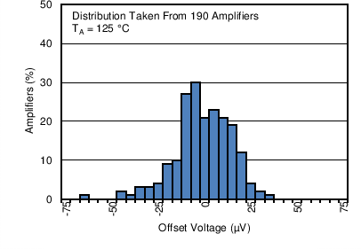
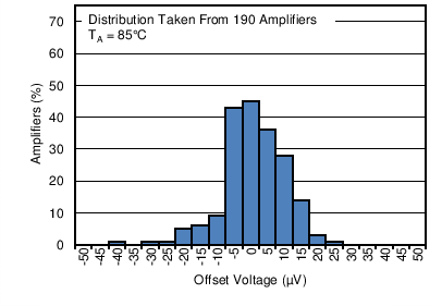
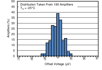
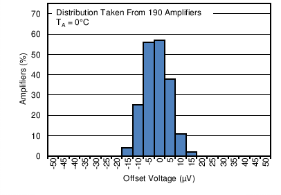
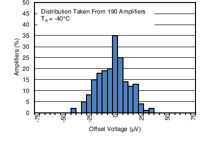
| Offset Voltage Production Distribution | Figure 1 to Figure 6 |
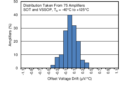
| Offset Voltage Drift Distribution | Figure 7 to Figure 10 |
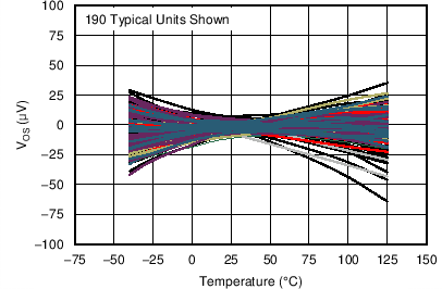
| Offset Voltage vs Temperature | Figure 11 |
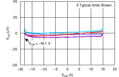
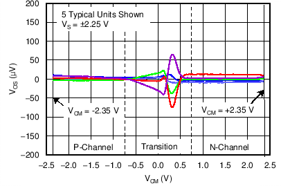
| Offset Voltage vs Common-Mode Voltage | Figure 12 to Figure 14 |
| Offset Voltage vs Power Supply | Figure 15 |
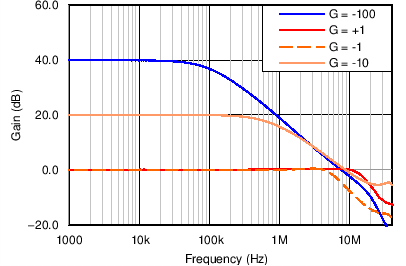
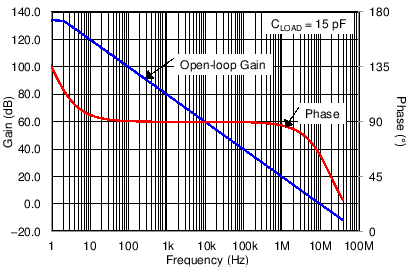
| Open-Loop Gain and Phase vs Frequency | Figure 16 |
| Closed-Loop Gain and Phase vs Frequency | Figure 17 |
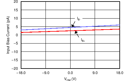
| Input Bias Current vs Common-Mode Voltage | Figure 18 |
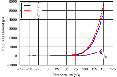
| Input Bias Current vs Temperature | Figure 19 |
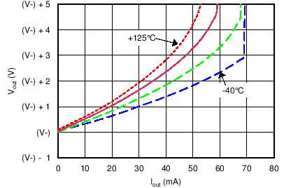
| Output Voltage Swing vs Output Current (maximum supply) | Figure 20 |
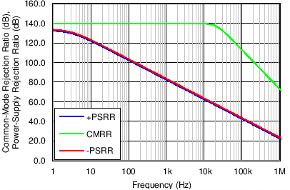
| CMRR and PSRR vs Frequency | Figure 21 |
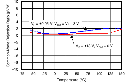
| CMRR vs Temperature | Figure 22 |
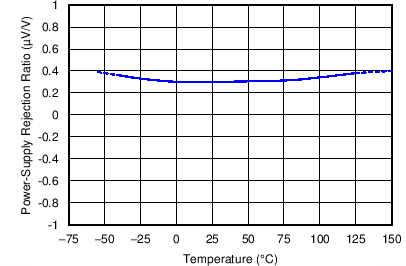
| PSRR vs Temperature | Figure 23 |
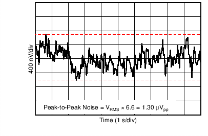
| 0.1-Hz to 10-Hz Noise | Figure 24 |
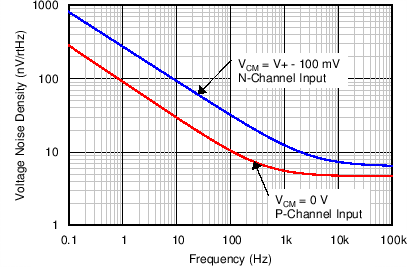
| Input Voltage Noise Spectral Density vs Frequency | Figure 25 |
| THD+N Ratio vs Frequency | Figure 26 |
| THD+N vs Output Amplitude | Figure 27 |
| Quiescent Current vs Supply Voltage | Figure 28 |
| Quiescent Current vs Temperature | Figure 29 |
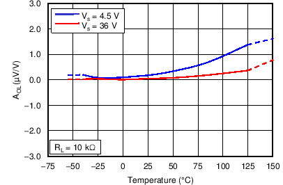
| Open Loop Gain vs Temperature | Figure 30 |
| Open Loop Output Impedance vs Frequency | Figure 31 |
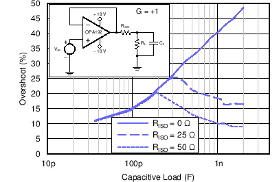
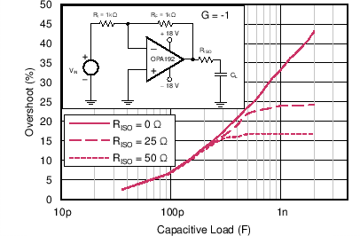
| Small Signal Overshoot vs Capacitive Load (100-mV Output Step) | Figure 32, Figure 33 |
| No Phase Reversal | Figure 34 |
| Positive Overload Recovery | Figure 35 |
| Negative Overload Recovery | Figure 36 |
| Small-Signal Step Response (100 mV) | Figure 37, Figure 38 |
| Large-Signal Step Response | Figure 39 |
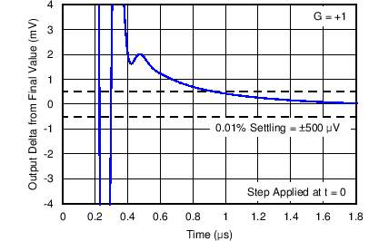
| Settling Time | Figure 40 to Figure 43 |
| Short-Circuit Current vs Temperature | Figure 44 |
| Maximum Output Voltage vs Frequency | Figure 45 |
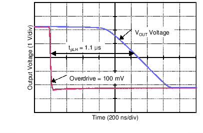
| Propagation Delay Rising Edge | Figure 46 |
| Propagation Delay Falling Edge | Figure 47 |
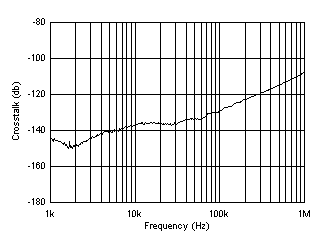
| Crosstalk vs Frequency | Figure 48 |
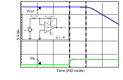
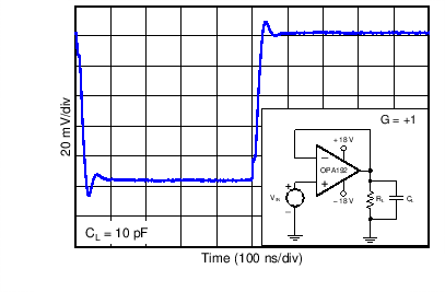
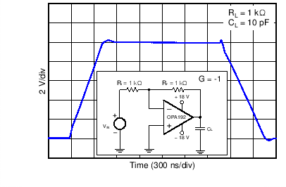
6.10 Typical Characteristics
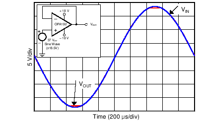
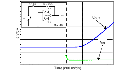
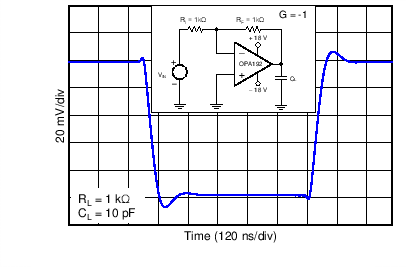
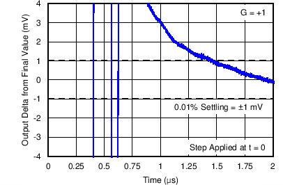
At TA = 25°C, VS = ±18 V, VCM = VS / 2, RLOAD = 10 kΩ connected to VS / 2, and CL = 100 pF, unless otherwise noted.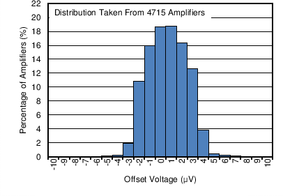
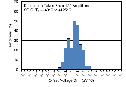
| OPA192ID and OPA2192ID |
from –40°C to +125°C
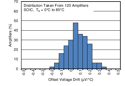
| OPA192ID and OPA2192ID |
from 0°C to 85°C
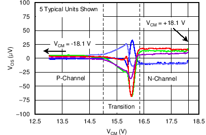
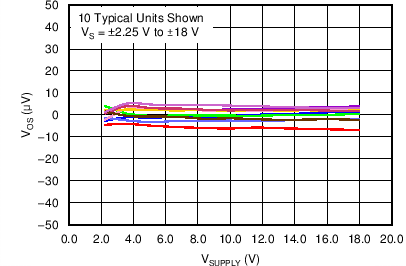
vs Frequency
(100-mV Output Step)


| OPA192IDBV, OPA192IDGK, OPA2192IDGK, and OPA4192IPW |
from –40°C to +125°C
| OPA192IDBV, OPA192IDGK, OPA2192IDGK, and OPA4192IPW |
from 0°C to 85°C
(100-mV Output Step)


7 Parameter Measurement Information
7.1 Input Offset Voltage Drift
The OPAx192 family of operational amplifiers is manufactured using TI’s e-trim technology. Each amplifier input offset voltage and input offset voltage drift is trimmed in production, thereby minimizing errors associated with input offset voltage and input offset voltage drift. The e-trim technology is a TI proprietary method of trimming internal device parameters during either wafer probing or final testing. When trimming input offset voltage drift the systematic or linear drift error on each device is trimmed to zero. This results in the remaining errors associated with input offset drift are minimal and are the result from only nonlinear error sources. Figure 49 illustrates this concept.
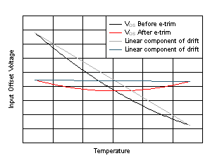 Figure 49. Input Offset Before and After Drift Trim
A common method of specifying input offset voltage drift is the box method. The box method estimates a maximum input offset drift by bounding the offset voltage versus temperature curve with a box and using the corners of this bounding box to determine the drift. The slope of the line connecting the diagonal corners of the box corresponds to the input offset voltage drift. Figure 50 shows the box method concept. The box method works particularly well when the input offset drift is dominated by the linear component of drift, but because the OPA192 family uses TI’s e-trim technology to remove the linear component input offset voltage drift, the box method is not a particularly useful method of accurately performing an error analysis. Figure 50 shows 30 typical units of the OPAx192 with the box method superimposed for illustrative purposes. The boundaries of the box are determined by the specified temperature range along the x-axis and the maximum specified input offset voltage across that same temperature range along the y-axis. Using the box method predicts an input offset voltage drift of 0.9 µV/°C. As shown in Figure 50, the slopes of the actual input offset voltage versus temperature are much less than that predicted by the box method. The box method predicts a pessimistic value for the maximum input offset voltage drift and is not recommended when performing an error analysis.
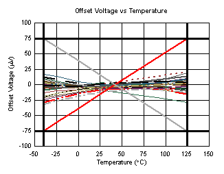 Figure 50. The Box Method
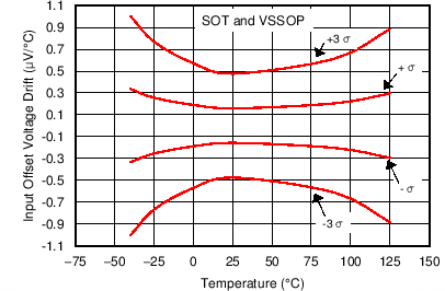
Instead of the box method, a convenient way to illustrate input offset drift is to compute the slopes of the input offset voltage versus temperature curve. This is the same as computing the input offset drift at each point along the input offset voltage versus temperature curve. The results for the OPAx192 family are shown in Figure 51 and Figure 52.
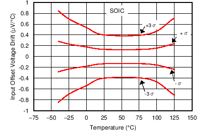 Figure 51. Input Offset Voltage Drift vs Temperature
(OPA192ID and OPA2192ID)
As shown in Figure 51, the input offset drift is typically less than ±0.3 µV/°C over the range from –40°C to +125°C. When performing an error analysis over the full specified temperature range, use the typical and maximum values for input offset voltage drift as described in the Electrical Characteristics tables. If a reduced temperature range is applicable, use the information shown in Figure 51 or Figure 52 when performing an error analysis. To determine the change in input offset voltage, use Equation 1:
where
- ΔVOS = Change in input offset voltage
- ΔT = Change in temperature
- dVOS/dT = Input offset voltage drift
For example, determine the amount of OPA192ID input offset voltage change over the temperature range of 25°C to 75°C for 1 σ (68%) of the units. As shown in Figure 51, the input offset drift is typically 0.15 µV/°C. This input offset drift results in a typical input offset voltage change of (75°C – 25°C) × 0.15 µV/°C = 7.5 µV .
For 3 σ (99.7%) of the units, Figure 51 shows a typical input offset drift of 0.4 µV/°C. This input offset drift results in a typical input offset voltage change of (75°C – 25°C) × 0.4 µV/°C = 20 µV.
Figure 53 shows six typical units.
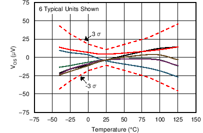 Figure 53. Input Offset Voltage Drift vs Temperature for Six Typical Units
