SLOS914 July 2016 OPA2317-Q1 , OPA317-Q1
PRODUCTION DATA.
- 1 Features
- 2 Applications
- 3 Description
- 4 Revision History
- 5 Pin Configuration and Functions
- 6 Specifications
- 7 Parameter Measurement Information
- 8 Detailed Description
- 9 Application and Implementation
- 10Power Supply Recommendations
- 11Layout
- 12Device and Documentation Support
- 13Mechanical, Packaging, and Orderable Information
Package Options
Mechanical Data (Package|Pins)
- DGK|8
Thermal pad, mechanical data (Package|Pins)
Orderable Information
11 Layout
11.1 Layout Guidelines
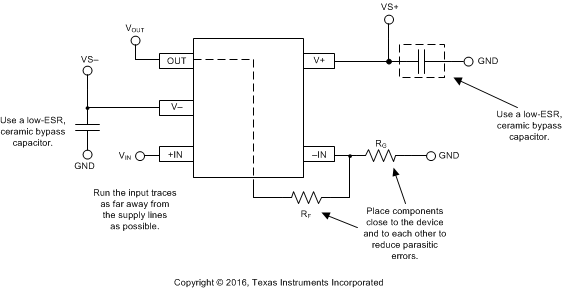
Attention to good layout practice is always recommended. Keep traces short and, when possible, use a printed-circuit board (PCB) ground plane with surface-mount components placed as close to the device pins as possible. Place a 0.1-μF capacitor closely across the supply pins. Apply these guidelines throughout the analog circuit to improve performance and provide benefits, such as reducing the electromagnetic interference (EMI) susceptibility.
Optimize circuit layout and mechanical conditions for lowest offset voltage and precision performance. Avoid temperature gradients that create thermoelectric (Seebeck) effects in the thermocouple junctions formed from connecting dissimilar conductors. These thermally-generated potentials can be made to cancel by assuring they are equal on both input terminals. Other layout and design considerations include:
- Use low thermoelectric-coefficient conditions (avoid dissimilar metals).
- Thermally isolate components from power supplies or other heat sources.
- Shield operational amplifier and input circuitry from air currents, such as cooling fans.
Following these guidelines reduces the likelihood of junctions being at different temperatures, which can cause thermoelectric voltage drift of 0.1 μV/°C or higher, depending on the materials used.
11.2 Layout Example
 Figure 25. OPAx317-Q1 Layout Example