SLOS856B June 2013 – May 2017 OPA2322-Q1 , OPA322-Q1 , OPA4322-Q1
PRODUCTION DATA.
- 1 Features
- 2 Applications
- 3 Description
- 4 Revision History
- 5 Pin Configuration and Functions
- 6 Specifications
- 7 Typical Characteristics
- 8 Detailed Description
- 9 Application and Implementation
- 10Power Supply Recommendations
- 11Layout
- 12Device and Documentation Support
- 13Mechanical, Packaging, and Orderable Information
Package Options
Mechanical Data (Package|Pins)
- DGK|8
Thermal pad, mechanical data (Package|Pins)
Orderable Information
7 Typical Characteristics
at TA = 25°C, VCM = VOUT = midsupply, and RL = 10 kΩ (unless otherwise noted)
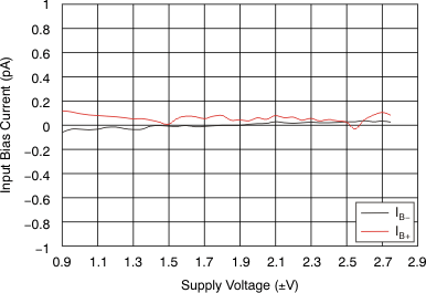 Figure 3. Input Bias Current vs Supply Voltage
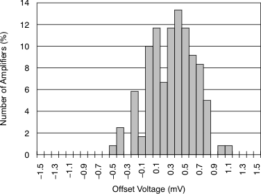
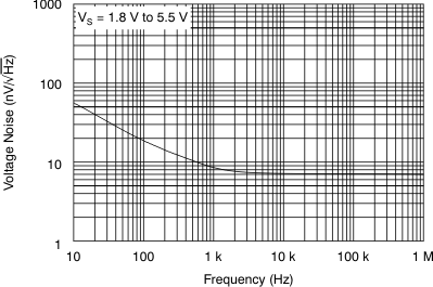
vs Frequency
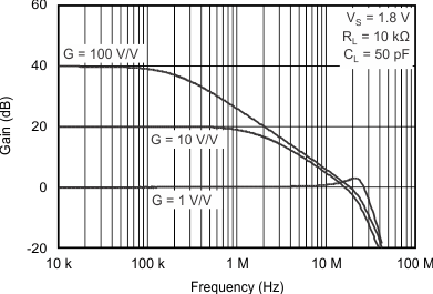 Figure 11. Closed-Loop Gain vs Frequency
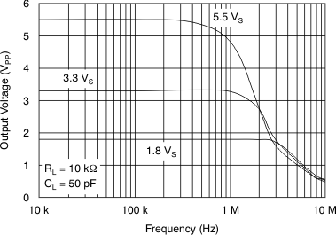 Figure 13. Maximum Output Voltage vs Frequency
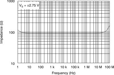 Figure 15. Open-Loop Output Impedance
vs Frequency
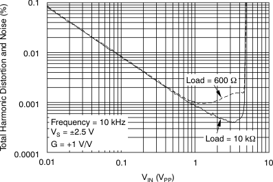 Figure 17. THD+N vs Amplitude
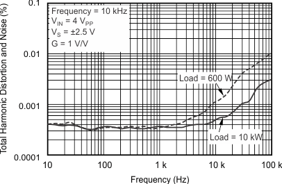 Figure 19. THD+N vs Frequency
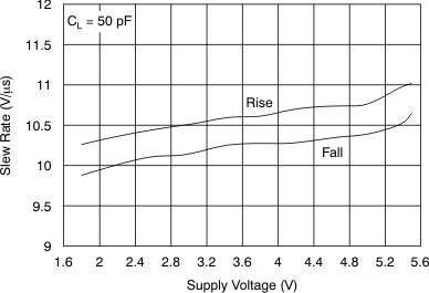 Figure 21. Slew Rate vs Supply Voltage
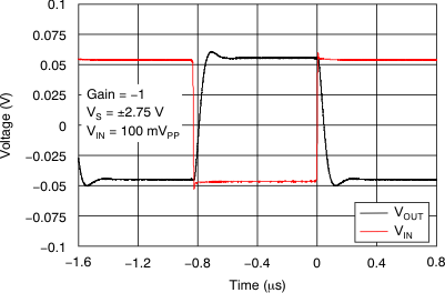 Figure 23. Small-Signal Step Response
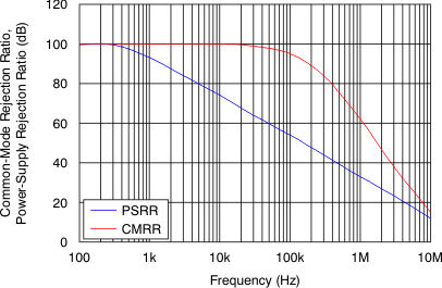 Figure 25. CMRR and PSRR vs Frequency
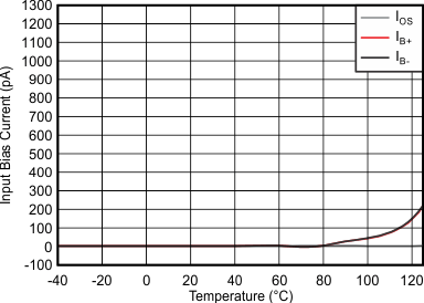
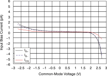 Figure 4. Input Bias Current
vs Common-Mode Voltage
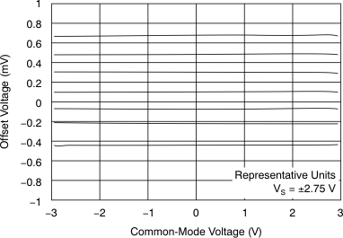
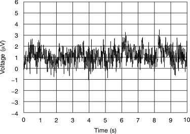
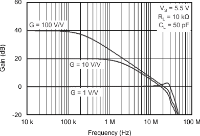 Figure 12. Closed-Loop Gain vs Frequency
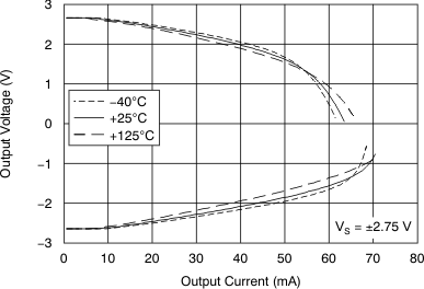 Figure 14. Output Voltage Swing vs Output Current
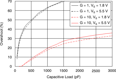 Figure 16. Small-Signal Overshoot
vs Load Capacitance
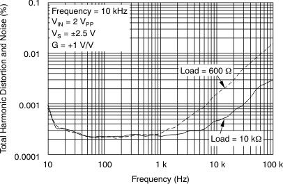 Figure 18. THD+N vs Frequency
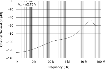 Figure 20. Channel Separation
vs Frequency (Dual-Channel)
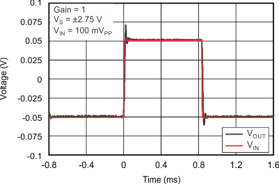 Figure 22. Small-Signal Step Response
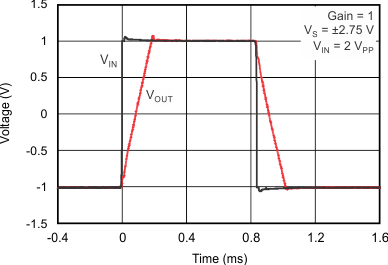 Figure 24. Large-Signal Step Response vs Time
