SBOS973A June   2019  – September 2019 OPA2834

PRODUCTION DATA.  

  1. Features
  2. Applications
  3. Description
    1.     Device Images
      1.      1-kHz FFT Plot (VOUT = 1 VRMS, RL = 100 kΩ, G = 1)
      2.      Low-Side, Current-Shunt Monitoring
  4. Revision History
  5. Device Comparison Table
  6. Pin Configuration and Functions
    1.     Pin Functions
  7. Specifications
    1. 7.1 Absolute Maximum Ratings
    2. 7.2 ESD Ratings
    3. 7.3 Recommended Operating Conditions
    4. 7.4 Thermal Information
    5. 7.5 Electrical Characteristics: 3V to 5V
    6. 7.6 Typical Characteristics: Vs = 5 V
    7. 7.7 Typical Characteristics: VS = 3.0 V
    8. 7.8 Typical Characteristics: ±2.5-V to ±1.5-V Split Supply
  8. Detailed Description
    1. 8.1 Overview
    2. 8.2 Functional Block Diagrams
    3. 8.3 Feature Description
      1. 8.3.1 Input Common-Mode Voltage Range
      2. 8.3.2 Output Voltage Range
      3. 8.3.3 Low-Power Applications and the Effects of Resistor Values on Bandwidth
      4. 8.3.4 Driving Capacitive Loads
    4. 8.4 Device Functional Modes
      1. 8.4.1 Split-Supply Operation (±1.35 V to ±2.7 V)
      2. 8.4.2 Single-Supply Operation (2.7 V to 5.4 V)
  9. Application and Implementation
    1. 9.1 Application Information
      1. 9.1.1 Noninverting Amplifier
      2. 9.1.2 Inverting Amplifier
    2. 9.2 Typical Applications
      1. 9.2.1 Low-Side Current Sensing
        1. 9.2.1.1 Design Requirements
        2. 9.2.1.2 Detailed Design Procedure
      2. 9.2.2 Field Transmitter Sensor Interface
      3. 9.2.3 Ultrasonic Flow Meters
      4. 9.2.4 Microphone Pre-Amplifier
  10. 10Power Supply Recommendations
  11. 11Layout
    1. 11.1 Layout Guidelines
    2. 11.2 Layout Examples
  12. 12Device and Documentation Support
    1. 12.1 Documentation Support
      1. 12.1.1 Related Documentation
    2. 12.2 Receiving Notification of Documentation Updates
    3. 12.3 Community Resources
    4. 12.4 Trademarks
    5. 12.5 Electrostatic Discharge Caution
    6. 12.6 Glossary
  13. 13Mechanical, Packaging, and Orderable Information

Package Options

Mechanical Data (Package|Pins)
Thermal pad, mechanical data (Package|Pins)
Orderable Information

Split-Supply Operation (±1.35 V to ±2.7 V)

To facilitate testing with common lab equipment, the OPA2834EVM (see the OPA2837DGK Evaluation Module user guide) is built to allow split-supply operation. This configuration eases lab testing because the mid-point between the power rails is ground, and most signal generators, network analyzers, oscilloscopes, spectrum analyzers, and other lab equipment have inputs and outputs with a ground reference.

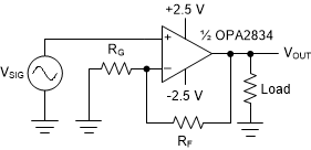
Figure 50 shows a simple noninverting configuration analogous to Figure 45 with a ±2.5-V supply and the reference voltage (VREF) equal to ground. The input and output swing symmetrically around ground. For ease of use, split supplies are preferred in systems where signals swing around ground.
OPA2834 Split_Supply_Operation.gifFigure 50. Split-Supply Operation