SBOS940A May 2019 – March 2020 OPA818
PRODUCTION DATA.
- 1 Features
- 2 Applications
- 3 Description
- 4 Revision History
- 5 Device Comparison Table
- 6 Pin Configuration and Functions
- 7 Specifications
- 8 Detailed Description
- 9 Application and Implementation
- 10Power Supply Recommendations
- 11Layout
- 12Device and Documentation Support
- 13Mechanical, Packaging, and Orderable Information
Package Options
Mechanical Data (Package|Pins)
- DRG|8
Thermal pad, mechanical data (Package|Pins)
- DRG|8
Orderable Information
3 Description
The OPA818 is a decompensated, voltage-feedback operational amplifier for high-speed and wide dynamic range applications. OPA818 has a low-noise junction gate field-effect transistor (JFET) input stage that combines high gain-bandwidth with a wide supply range from 6 V to 13 V. The fast slew rate of
1400 V/µs provides high large-signal bandwidth and low distortion. This amplifier is manufactured using Texas Instruments' proprietary, high-speed, silicon-germanium (SiGe) process to achieve significant performance improvements over other high-speed, FET-input amplifiers.
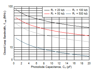
The OPA818 is an extremely versatile, wideband TIA photodiode amplifier for use in optical test and communication equipment, and many medical, scientific, and industrial instruments. The OPA818 showcases 2.7 GHz gain-bandwidth, low 2.4 pF total input capacitance, and 2.2 nV/√Hz input noise. The OPA818 can achieve over 85-MHz signal bandwidth in TIA configuration with 20-kΩ TIA gain (RF) and
0.5-pF photodiode capacitance (CD) with wide output swings. The decompensated, low-noise architecture with pico amperes of input bias current is also well-suited for high-gain test and measurement applications. Though normally stable in gains ≥ 7 V/V, the OPA818 can be used in applications with lower gains by applying noise-gain shaping techniques (see Non-Inverting Gain of 2 V/V).
The OPA818 is available in an 8-lead WSON package with an exposed thermal pad for heat dissipation. This device is specified to operate over the industrial temperature range of –40°C to +85°C.
Device Information(1)
| PART NUMBER | PACKAGE | BODY SIZE (NOM) |
|---|---|---|
| OPA818 | WSON (8) | 3.00 mm × 3.00 mm |
- For all available packages, see the package option addendum at the end of the data sheet.
Photodiode Capacitance vs 3-dB Bandwidth
