SBOSA57B February 2021 – January 2023 OPA855-Q1
PRODUCTION DATA
- 1 Features
- 2 Applications
- 3 Description
- 4 Revision History
- 5 Device Comparison Table
- 6 Pin Configuration and Functions
- 7 Specifications
- 8 Parameter Measurement Information
- 9 Detailed Description
- 10Application, Implementation, and Layout
- 11Power Supply Recommendations
- 12Layout
- 13Device and Documentation Support
- 14Mechanical, Packaging, and Orderable Information
Package Options
Mechanical Data (Package|Pins)
- DSG|8
Thermal pad, mechanical data (Package|Pins)
- DSG|8
Orderable Information
8 Parameter Measurement Information
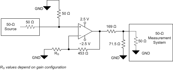
The various test setup configurations for the OPA855-Q1 are shown in Figure 8-1, Figure 8-2, and Figure 8-3. When configuring the OPA855-Q1 in a gain of +39.2 V/V, feedback resistor RF was set to 953 Ω.
Figure 7-1 shows 5-dB of peaking with the amplifier in an inverting configuration of –7 V/V with the amplifier configured as shown in Figure 8-2. The 50-Ω matched termination of this circuit configuration results in the amplifier being configured in a noise gain of 5.3 V/V, which is lower than the recommended +7 V/V.
 Figure 8-1 Noninverting Configuration
 Figure 8-2 Inverting Configuration (Gain = –7 V/V)
 Figure 8-3 Capacitive Load Driver Configuration