-
PCM175x-Q1 24-Bit 192-kHz Sampling Enhanced Multi-Level Delta-Sigma Audio Digital-to-Analog Converter SLES254D April 2010 – July 2015 PCM1753-Q1 , PCM1754-Q1
PRODUCTION DATA.
-
PCM175x-Q1 24-Bit 192-kHz Sampling Enhanced Multi-Level Delta-Sigma Audio Digital-to-Analog Converter
- 1 Features
- 2 Applications
- 3 Description
- 4 Revision History
- 5 Device Comparison Table
- 6 Pin Configuration Functions
- 7 Specifications
-
8 Detailed Description
- 8.1 Overview
- 8.2 Functional Block Diagram
- 8.3 Feature Description
- 8.4 Device Functional Modes
- 8.5 Programming
- 8.6
Register Maps
- 8.6.1
Mode Control Registers (PCM1753-Q1)
- 8.6.1.1 User-Programmable Mode Controls
- 8.6.1.2
Register Definitions
- 8.6.1.2.1 ATx[7:0]: Digital Attenuation Level Setting
- 8.6.1.2.2 MUTx: Soft Mute Control
- 8.6.1.2.3 OVER: Oversampling Rate Control
- 8.6.1.2.4 SRST: Reset
- 8.6.1.2.5 DACx: DAC Operation Control
- 8.6.1.2.6 DM12: Digital De-Emphasis Function Control
- 8.6.1.2.7 DMF[1:0]: Sampling Frequency Selection for the De-Emphasis Function
- 8.6.1.2.8 FMT[2:0]: Audio Interface Data Format
- 8.6.1.2.9 FLT: Digital Filter Rolloff Control
- 8.6.1.2.10 DREV: Output Phase Select
- 8.6.1.2.11 ZREV: Zero Flag Polarity Select
- 8.6.1.2.12 AZRO: Zero Flag Function Select
- 8.6.1
Mode Control Registers (PCM1753-Q1)
- 9 Application and Implementation
- 10Power Supply Recommendations
- 11Layout
- 12Device and Documentation Support
- 13Mechanical, Packaging, and Orderable Information
- IMPORTANT NOTICE
Package Options
Mechanical Data (Package|Pins)
- DBQ|16
Thermal pad, mechanical data (Package|Pins)
Orderable Information
PCM175x-Q1 24-Bit 192-kHz Sampling Enhanced Multi-Level Delta-Sigma Audio Digital-to-Analog Converter
1 Features
- Qualified for Automotive Applications
- AEC-Q100 Qualified With the Following Results:
- 24-Bit Resolution
- Analog Performance (VCC = 5 V)
- Dynamic Range: 106 dB
- SNR: 106 dB, Typical
- THD+N: 0.002%, Typical
- Full-Scale Output: 4 VPP, Typical
- 4× and 8× Oversampling Digital Filter
- Stop-Band Attenuation: –50 dB
- Pass-Band Ripple: ±0.04 dB
- Sampling Frequency: 5 kHz to 200 kHz
- System Clock: 128 fS, 192 fS, 256 fS, 384 fS,
512 fS, 768 fS, 1152 fS with Auto Detect - Hardware Control (PCM1754-Q1)
- I2S and 16-Bit Word, Right-Justified
- 44.1 kHz Digital De-Emphasis
- Soft Mute
- Zero Flag for L-, R-Channel Common Output
- Power Supply: 5-V Single Supply
- Small 16-Lead SSOP Package, Lead-Free
2 Applications
3 Description
The PCM175x-Q1 family of devices is a CMOS, monolithic, integrated circuit, which includes stereo digital-to-analog converters and support circuitry in a small 16-lead SSOP package. The data converters use TI's enhanced multilevel delta-sigma architecture, which employs 4th-order noise shaping and 8-level amplitude quantization to achieve excellent dynamic performance and improved tolerance to clock jitter. The PCM175x-Q1 family of devices accepts industry-standard audio data formats with 16- to 24-bit data, providing easy interfacing to audio DSP and decoder chips. Sampling rates up to 200 kHz are supported. A full set of user-programmable functions is accessible through a three-wire serial control port, which supports register write functions.
The PCM1753-Q1 device is pin-compatible with the PCM1748, PCM1742, and PCM1741 devices, except for pin 5.
Device Information(1)
| PART NUMBER | PACKAGE | BODY SIZE (NOM) |
|---|---|---|
| PCM1753-Q1 | SSOP (16) | 4.90 mm × 3.90 mm |
| PCM1754-Q1 |
- For all available packages, see the orderable addendum at the end of the data sheet.
Functional Block Diagram

4 Revision History
Changes from C Revision (October 2012) to D Revision
- Changed device temperature grade from 1 to 2 in the Features list Go
- Added the ESD Ratings table, Feature Description section, Device Functional Modes section, Application and Implementation section, Power Supply Recommendations section, Layout section, Device and Documentation Support section, and Mechanical, Packaging, and Orderable Information section Go
Changes from B Revision (December 2011) to C Revision
5 Device Comparison Table
| FEATURE | PCM1753-Q1 | PCM1754-Q1 |
|---|---|---|
| Audio-data interface format | I2S, standard, left-justified | I2S, standard |
| Audio-data bit length | 16-bit, 18-bit, 20-bit, and 24-bit selectable | 16-bit and 24-bit I2S, 16-bit standard |
| Audio data format | MSB first, 2s complement | |
6 Pin Configuration Functions

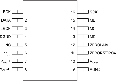
Pin Functions—PCM1753-Q1
| PIN | I/O | DESCRIPTION | |
|---|---|---|---|
| NAME | NO. | ||
| AGND | 9 | — | Analog ground |
| BCK | 1 | I | Audio–data bit–clock input |
| DATA | 2 | I | Audio–data digital input |
| DGND | 4 | I | Digital ground |
| LRCK | 3 | — | L-channel and R-channel audio data latch enable input |
| MC | 14 | I | Mode control clock input(1) |
| MD | 13 | I | Mode control data input(1) |
| ML | 15 | I | Mode control latch input(1) |
| NC | 5 | — | No connection |
| SCK | 16 | I | System clock input |
| VCC | 6 | I | Analog power supply, 5 V |
| VCOM | 10 | — | Common voltage decoupling |
| VOUTL | 7 | — | Analog output for the L-channel |
| VOUTR | 8 | O | Analog output for the R-channel |
| ZEROR/ZEROA | 11 | O | Zero flag output for the R-channel. This pin is also the zero flag output for the L-channel and R-channel(2). |
| ZEROL/NA | 12 | O | Zero flag output fo the L-channel. Not assigned(2) |

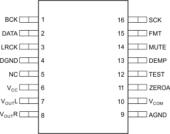
Pin Functions—PCM1754-Q1
| PIN | I/O | DESCRIPTION | |
|---|---|---|---|
| NAME | NO. | ||
| AGND | 9 | — | Analog ground |
| BCK | 1 | I | Audio–data bit–clock input |
| DATA | 2 | I | Audio–data digital input |
| DEMP | 13 | I | De–emphasis control(1) |
| DGND | 4 | — | Digital ground |
| FMT | 15 | I | Data format select(1) |
| LRCK | 3 | I | L–channel and R–channel audio data latch enable input |
| MUTE | 14 | I | Analog mixing control(1) |
| NC | 5 | — | No connection |
| SCK | 16 | I | System clock input |
| TEST | 12 | I | Test pin. Ground or open(1) |
| VCC | 6 | — | Analog power supply, 5 V |
| VCOM | 10 | — | Common voltage decoupling |
| VOUTL | 7 | O | Analog output for the L–channel |
| VOUTR | 8 | O | Analog output for the R–channel |
| ZEROA | 11 | O | Zero flag output for the L-channel and R-channel |