-
PCM270xC Stereo Audio DAC With USB Interface, Single-Ended Headphone Output and S/PDIF Output
- 1 Features
- 2 Applications
- 3 Description
- 4 Revision History
- 5 Device Comparison Table
- 6 Pin Configuration and Functions
-
7 Specifications
- 7.1 Absolute Maximum Ratings
- 7.2 ESD Ratings
- 7.3 Recommended Operating Conditions
- 7.4 Thermal Information: PCM2704C, PCM2705C
- 7.5 Thermal Information: PCM2706C, PCM2707C
- 7.6 Electrical Characteristics: PCM2704CDB, PCM2705CDB, PCM2706CPJT, PCM2707CPJT
- 7.7 Audio Interface Timing Characteristics
- 7.8 Audio Clock Timing Characteristics
- 7.9 External ROM Read Interface Timing Characteristics
- 7.10 SPI Timing Characteristics
- 7.11 Typical Characteristics
- 8 Parameter Measurement Information
-
9 Detailed Description
- 9.1 Overview
- 9.2 Functional Block Diagrams
- 9.3
Feature Description
- 9.3.1 Clock and Reset
- 9.3.2 Operation Mode Selection
- 9.3.3 DAC
- 9.3.4 Digital Audio Interface: S/PDIF Output
- 9.3.5 Digital Audio Interface: I2S Interface Output (PCM2706C/7C)
- 9.3.6 Descriptor Data Modification
- 9.3.7 External ROM Descriptor (PCM2704C/6C)
- 9.3.8 External ROM Example
- 9.3.9 Serial Programming Interface (PCM2705C/7C)
- 9.3.10 USB Host Interface Sequence
- 9.3.11 Operating Environment
- 9.4 Device Functional Modes
- 9.5 Programming
- 9.6 Register Maps
- 10Application and Implementation
- 11Power Supply Recommendations
- 12Layout
- 13Device and Documentation Support
- 14Mechanical, Packaging, and Orderable Information
- IMPORTANT NOTICE
Package Options
Mechanical Data (Package|Pins)
- DB|28
Thermal pad, mechanical data (Package|Pins)
Orderable Information
DATA SHEET
PCM270xC Stereo Audio DAC With USB Interface, Single-Ended Headphone Output and S/PDIF Output
1 Features
- On-Chip USB Interface:
- Sampling Rates: 32 kHz, 44.1 kHz, and 48 kHz
- On-Chip Clock Generator With Single 12-MHz Clock Source
- Single Power Supply:
- Bus-Powered: 5 V, Typical (VBUS)
- Self-Powered: 3.3 V, Typical
- 16-Bit Delta-Sigma Stereo DAC
- Analog Performance at 5 V (Bus-Powered),
3.3 V (Self-Powered):- THD + N: 0.006% RL > 10 kΩ, Self-Powered
- THD + N: 0.025% RL = 32 Ω
- SNR = 98 dB
- Dynamic Range: 98 dB
- PO = 12 mW, RL = 32 Ω
- Oversampling Digital Filter
- Passband Ripple = ±0.04 dB
- Stop-Band Attenuation = –50 dB
- Single-Ended Voltage Output
- Analog LPF Included
- Analog Performance at 5 V (Bus-Powered),
- Multiple Functions:
- Up to Eight Human Interface Device (HID) Interfaces (Model and Setting Dependent)
- Suspend Flag
- S/PDIF Out With SCMS
- External ROM Interface (PCM2704C/6C)
- Serial Programming Interface (PCM2705C/7C)
- I2S Interface (Selectable on PCM2706C/7C)
2 Applications
- USB Headphones
- USB Audio Speaker
- USB CRT/LCD Monitor
- USB Audio Interface Box
- USB-Featured Consumer Audio Product
3 Description
The PCM270xC are TI's single-chip USB stereo audio digital-to-analog converters (DACs) with USB 2.0 compliant full-speed protocol controller and S/PDIF. The USB-protocol controller works with no software code, but USB descriptors can be modified in some areas (for example, vendor ID/product ID) through the use of an external ROM (PCM2704C and PCM2706C) or serial peripheral interface (SPI) (PCM2705C and PCM2707C). The PCM270xC also employ SpAct™ architecture, TI's unique system that recovers the audio clock from USB packet data. On-chip analog phase-locked loops (PLLs) with SpAct enable playback with low clock jitter.
Device Information(1)
| PART NUMBER | PACKAGE | BODY SIZE (NOM) |
|---|---|---|
| PCM2704C | SSOP (28) | 5.30 mm × 10.20 mm |
| PCM2705C | ||
| PCM2706C | TQFP (32) | 7.00 mm × 7.00 mm |
| PCM2707C |
- For all available packages, see the orderable addendum at the end of the data sheet.
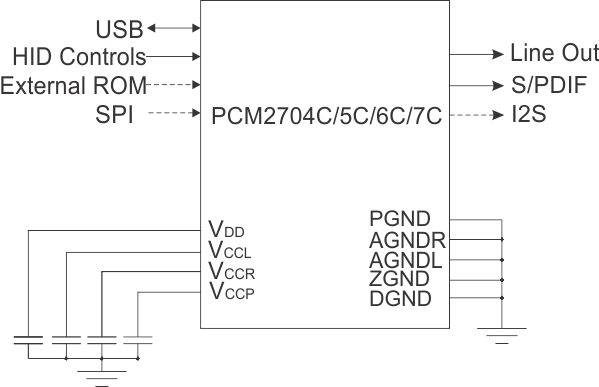
Block Diagram

4 Revision History
Changes from A Revision (July 2012) to B Revision
- Added Handling Ratings table, Feature Description section, Device Functional Modes, Application and Implementation section, Power Supply Recommendations section, Layout section, Device and Documentation Support section, and Mechanical, Packaging, and Orderable Information section Go
Changes from * Revision (August 2011) to A Revision