SLTS278J November 2010 – March 2020 PTH08T250W
PRODUCTION DATA.
- 1 Features
- 2 Applications
- 3 Description
- 4 Revision History
- 5 Description (continued)
- 6 Pin Configuration and Functions
- 7 Specifications
- 8 Detailed Description
-
9 Application and Implementation
- 9.1
Typical Application
- 9.1.1
Detailed Design Procedure
- 9.1.1.1 Adjusting the Output Voltage
- 9.1.1.2
Capacitor Recommendations for the PTH08T250W Power Module
- 9.1.1.2.1 Capacitor Technologies
- 9.1.1.2.2 Input Capacitor (Required)
- 9.1.1.2.3 Input Capacitor Information
- 9.1.1.2.4 Output Capacitor (Required)
- 9.1.1.2.5 Output Capacitor Information
- 9.1.1.2.6 TurboTrans Output Capacitance
- 9.1.1.2.7 Non-TurboTrans Output Capacitance
- 9.1.1.2.8 Designing for Fast Load Transients
- 9.1.1.2.9 Capacitor Table
- 9.1.1.3 TurboTrans™ Technology
- 9.1.1.4 TurboTrans™ Selection
- 9.1.1.5 Undervoltage Lockout (UVLO)
- 9.1.1.6 On/Off Inhibit
- 9.1.1.7 Current Sharing
- 9.1.1.8 Prebias Startup Capability
- 9.1.1.9 SmartSync Technology
- 9.1.1.10 Auto-Track™ Function
- 9.1.1
Detailed Design Procedure
- 9.1
Typical Application
- 10Device and Documentation Support
- 11Mechanical, Packaging, and Orderable Information
Package Options
Refer to the PDF data sheet for device specific package drawings
Mechanical Data (Package|Pins)
- BCU|22
- ECT|22
- ECU|22
Thermal pad, mechanical data (Package|Pins)
Orderable Information
9.1.1.6 On/Off Inhibit
For applications requiring output voltage on/off control, the PTH08T250W incorporates an Inhibit control pin. The inhibit feature can be used wherever there is a requirement for the output voltage from the regulator to be turned off. The power modules function normally when the Inhibit pin is left open-circuit, providing a regulated output whenever a valid source voltage is connected to VI with respect to GND.
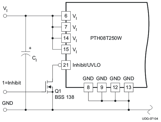
Figure 20 shows the typical application of the inhibit function. Note the discrete transistor (Q1). The Inhibit input has its own internal pull-up. An external pull-up resistor should never be used with the inhibit pin. The input is not compatible with TTL logic devices. An open-collector (or open-drain) discrete transistor is recommended for control.
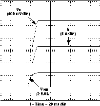
Turning Q1 on applies a low voltage to the Inhibit control pin and disables the output of the module. If Q1 is then turned off, the module executes a soft-start power-up sequence. A regulated output voltage is produced within 20 ms. Figure 21 shows the typical rise in both the output voltage and input current, following the turn-off of Q1. The turn off of Q1 corresponds to the rise in the waveform, VINH. The waveforms were measured with a 25-A constant current load.
 Figure 20. On/Off Inhibit Control Circuit
  Figure 21. Power-Up Response from Inhibit Control