-
REF31xx 15ppm/°C Maximum, 100-µA, SOT-23 Series Voltage Reference
- 1 Features
- 2 Applications
- 3 Description
- 4 Revision History
- 5 Device Comparison Table
- 6 Pin Configuration and Functions
- 7 Specifications
- 8 Detailed Description
- 9 Application and Implementation
- 10Power Supply Recommendations
- 11Layout
- 12Device and Documentation Support
- 13Mechanical, Packaging, and Orderable Information
- IMPORTANT NOTICE
Package Options
Refer to the PDF data sheet for device specific package drawings
Mechanical Data (Package|Pins)
- DBZ|3
Thermal pad, mechanical data (Package|Pins)
Orderable Information
REF31xx 15ppm/°C Maximum, 100-µA, SOT-23 Series Voltage Reference
1 Features
2 Applications
- Portable, Battery-Powered Equipment
- Data Acquisition Systems
- Medical Equipment
- Hand-Held Test Equipment
3 Description
The REF31xx is a family of precision, low power, low dropout, series voltage references available in the tiny 3-pin SOT-23 package.
The REF31xx's small size and low power consumption (100 μA typical) make it ideal for portable and battery-powered applications. The REF31xx does not require a load capacitor, but is stable with any capacitive load and can sink or source up to 10 mA of output current.
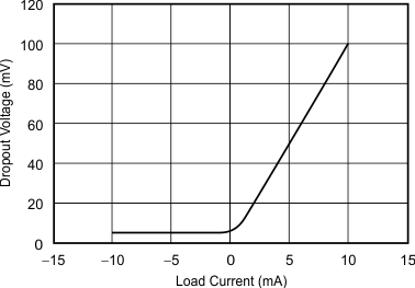
Unloaded, the REF31xx can operate on supplies down to 5 mV above the output voltage. All models are specified for the wide temperature range of –40°C to +125°C.
Device Information(1)
| PART NUMBER | PACKAGE | BODY SIZE (NOM) |
|---|---|---|
| REF31xx | SOT-23 (3) | 2.92 mm × 1.30 mm |
- For all available packages, see the orderable addendum at the end of the data sheet.
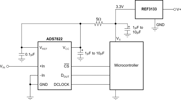
Typical Application
Dropout Voltage vs Load Current
4 Revision History
Changes from C Revision (February 2006) to D Revision
- Added the Device Information table, the Thermal Information table, Feature Description section, Device Functional Modes, Application and Implementation section, Power Supply Recommendations section, Layout section, Device and Documentation Support section, and Mechanical, Packaging, and Orderable Information section.Go
- Removed the Ordering Information table Go
- Moved and updated the SOT23-3 surface mount thermal resistance data from the Electrical Characteristics table to the Thermal Information tableGo
- Removed the boldface type in the Electrical Characteristics table and identified when limits apply over the specified temperature range TA = –40°C to +125°C in the test conditions column Go
- Added Figure 19Go
5 Device Comparison Table
| PRODUCT | VOLTAGE (V) |
|---|---|
| REF3112 | 1.25 |
| REF3120 | 2.048 |
| REF3125 | 2.5 |
| REF3130 | 3 |
| REF3133 | 3.3 |
| REF3140 | 4.096 |
6 Pin Configuration and Functions
Pin Functions
| PIN | I/O | DESCRIPTION | |
|---|---|---|---|
| NO. | NAME | ||
| 1 | IN | I | Input supply voltage |
| 2 | OUT | O | Reference output voltage |
| 3 | GND | — | Ground |
7 Specifications
7.1 Absolute Maximum Ratings
over operating free-air temperature range (unless otherwise noted)(1)| MIN | MAX | UNIT | ||
|---|---|---|---|---|
| Supply voltage, V+ to V– | 7 | V | ||
| Output short circuit | Continuous | |||
| Operating temperature | –55 | 135 | °C | |
| Junction temperature | 150 | °C | ||
| Storage temperature, Tstg | –65 | 150 | °C | |
7.2 ESD Ratings
| VALUE | UNIT | |||
|---|---|---|---|---|
| V(ESD) | Electrostatic discharge | Human-body model (HBM), per ANSI/ESDA/JEDEC JS-001(1) | ±2000 | V |
| Charged-device model (CDM), per JEDEC specification JESD22-C101(2) | ±1000 | |||
7.3 Recommended Operating Conditions
over operating free-air temperature range (unless otherwise noted)| MIN | MAX | UNIT | ||
|---|---|---|---|---|
| VIN | Input voltage | VREF + 0.05(1) | 5.5 | V |
| ILOAD | Load current | 25 | mA | |
| TA | Operating temperature | –40 | 125 | °C |
7.4 Thermal Information
| THERMAL METRIC(1) | REF31xx | UNIT | |
|---|---|---|---|
| DBZ (SOT-23) | |||
| 3 PINS | |||
| RθJA | Junction-to-ambient thermal resistance | 292.9 | °C/W |
| RθJC(top) | Junction-to-case (top) thermal resistance | 124.4 | °C/W |
| RθJB | Junction-to-board thermal resistance | 89 | °C/W |
| ψJT | Junction-to-top characterization parameter | 11.4 | °C/W |
| ψJB | Junction-to-board characterization parameter | 87.6 | °C/W |
| RθJC(bot) | Junction-to-case (bottom) thermal resistance | — | °C/W |
7.5 Electrical Characteristics
at TA = 25°C, ILOAD = 0 mA, and VIN = 5 V (unless otherwise noted)| PARAMETER | TEST CONDITIONS | MIN | TYP | MAX | UNIT | |||
|---|---|---|---|---|---|---|---|---|
| REF3312(1) — 1.25 V | ||||||||
| VOUT | Output voltage | 1.2475 | 1.25 | 1.2525 | V | |||
| Initial accuracy | –0.2% | 0.2% | ||||||
| Output voltage noise | f = 0.1 Hz to 10 Hz | 17 | μVPP | |||||
| f = 10 Hz to 10 kHz | 24 | μVRMS | ||||||
| REF3120 — 2.048 V | ||||||||
| VOUT | Output voltage | 2.0439 | 2.048 | 2.0521 | V | |||
| Initial accuracy | –0.2% | 0.2% | ||||||
| Output voltage noise | f = 0.1Hz to 10Hz | 27 | μVPP | |||||
| f = 10Hz to 10kHz | 39 | μVRMS | ||||||
| REF3125 — 2.5 V | ||||||||
| VOUT | Output voltage | 2.495 | 2.5 | 2.505 | V | |||
| Initial accuracy | –0.2% | 0.2% | ||||||
| Output voltage noise | f = 0.1Hz to 10Hz | 33 | μVPP | |||||
| f = 10Hz to 10kHz | 48 | μVRMS | ||||||
| REF3130 — 3 V | ||||||||
| VOUT | Output voltage | 2.994 | 3 | 3.006 | V | |||
| Initial accuracy | –0.2% | 0.2% | ||||||
| Output voltage noise | f = 0.1Hz to 10Hz | 39 | μVPP | |||||
| f = 10Hz to 10kHz | 57 | μVRMS | ||||||
| REF3133 — 3.3 V | ||||||||
| VOUT | Output voltage | 3.2934 | 3.3 | 3.3066 | V | |||
| Initial accuracy | –0.2% | 0.2% | ||||||
| Output voltage noise | f = 0.1Hz to 10Hz | 43 | μVPP | |||||
| f = 10Hz to 10kHz | 63 | μVRMS | ||||||
| REF3140 — 4.096 V | ||||||||
| VOUT | Output voltage | 4.0878 | 4.096 | 4.1042 | V | |||
| Initial accuracy | –0.2% | 0.2% | ||||||
| Output voltage noise | f = 0.1Hz to 10Hz | 53 | μVPP | |||||
| f = 10Hz to 10kHz | 78 | μVRMS | ||||||
| REF31xx (REF3112, REF3120, REF3125, REF3130, REF3133, REF3140) | ||||||||
| dVOUT/dT | Output voltage temperature drift(2) | TA = 0°C to 70°C. | 5 | 15 | ppm/°C | |||
| TA = –40°C to +125°C . | 10 | 20 | ||||||
| Long-term stability | 0 to 1000 hours | 70 | ppm | |||||
| Line regulation | VREF + 0.05(1) ≤ VIN ≤ 5.5V | 20 | 65 | ppm/V | ||||
| dVOUT/dILOAD | Load regulation(3) | Sourcing | 0mA < ILOAD < 10mA, VIN = VREF + 250mV(1) | 10 | 30 | µV/mA | ||
| Sinking | –10mA < ILOAD < 0mA, VIN = VREF + 100mV(1) | 20 | 50 | |||||
| dT | Thermal hysteresis(4) | First Cycle | 100 | ppm | ||||
| Additional Cycles | 25 | |||||||
| VIN – VOUT | Dropout voltage(1) | TA = –40°C to +125°C. | 5 | 50 | mV | |||
| ILOAD | Output current | –10 | 10 | mA | ||||
| ISC | Short-circuit current | Sourcing | 50 | mA | ||||
| Sinking | 40 | |||||||
| Turnon settling time | To 0.1% at VIN = +5V with CL = 0μF | 400 | µs | |||||
| POWER SUPPLY | ||||||||
| VS | Voltage | ILOAD = 0, TA = –40°C to +125°C. | VREF + 0.05(1) | 5.5 | V | |||
| IQ | Quiescent current | ILOAD = 0, TA = 25°C | 100 | 115 | µA | |||
| ILOAD = 0, TA = –40°C to +125°C | 115 | 135 | ||||||
7.6 Typical Characteristics
At TA = 25°C, VIN = 5-V power supply, and REF3125 is used for typical characteristic measurements, unless otherwise noted.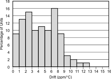 Figure 1. Temperature Drift (0°C to 70°C)
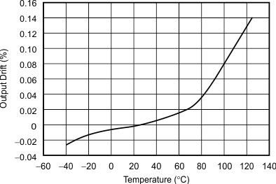 Figure 3. Output Voltage vs Temperature
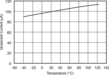 Figure 5. Quiescent Current vs Temperature
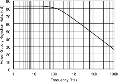 Figure 7. PSRR vs Frequency
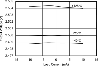 Figure 9. Output Voltage vs Load Current
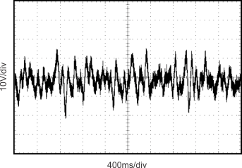 Figure 11. 0.1-Hz to 10-Hz Noise
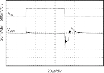 Figure 13. Line Transient CL = 0 pF
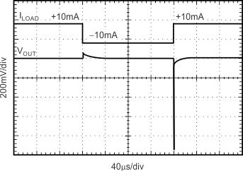 Figure 15. Load Transient CL = 0 pF, ±10-mA Output Pulse
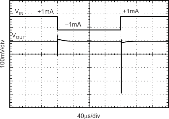 Figure 17. Load Transient CL = 0 pF, ±1-mA Output Pulse
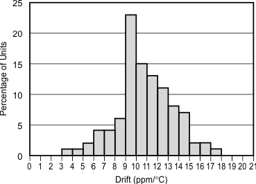 Figure 2. Temperature Drift (–40°C to +125°C)
 Figure 4. Dropout Voltage vs Load Current
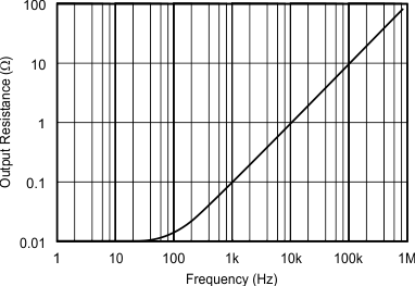 Figure 6. Output Impedance vs Frequency
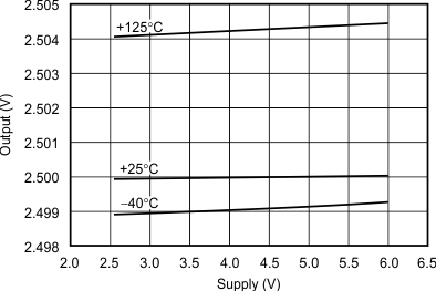 Figure 8. Output vs Supply
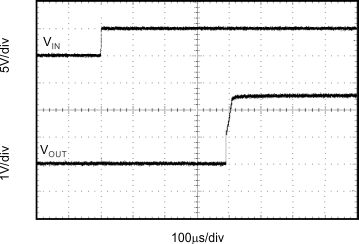 Figure 10. Step Response, CL = 0, 5-V Start-Up
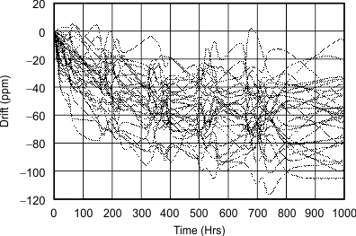 Figure 12. REF3112 Long-Term Stability
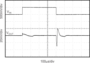 Figure 14. Line Transient CL = 10 μF
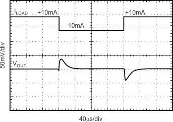 Figure 16. Load Transient CL = 1 µF, ±10-mA Output Pulse
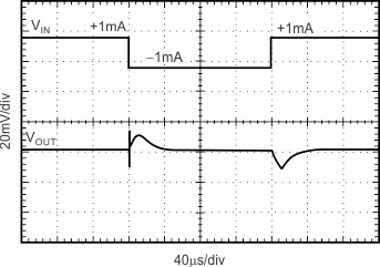 Figure 18. Load Transient CL = 1 µF, ±1-mA Output Pulse
8 Detailed Description
8.1 Overview
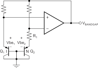
The REF31xx is a family of series, CMOS, precision bandgap voltage references. The basic bandgap topology is shown in Functional Block Diagram. Transistors Q1 and Q2 are biased such that the current density of Q1 is greater than that of Q2. The difference of the two base-emitter voltages, Vbe1 – Vbe2, has a positive temperature coefficient and is forced across resistor R1. This voltage is gained up and added to the base-emitter voltage of Q2, which has a negative temperature coefficient. The resulting output voltage is virtually independent of temperature. The curvature of the bandgap voltage, as shown in Figure 3, is due to the slightly nonlinear temperature coefficient of the base-emitter voltage of Q2.
8.2 Functional Block Diagram
8.3 Feature Description
8.3.1 Supply Voltage
The REF31xx family of references features an extremely low dropout voltage. With the exception of the REF3112, which has a minimum supply requirement of 1.8 V, these references can be operated with a supply of only 5 mV above the output voltage in an unloaded condition. For loaded conditions, a typical dropout voltage versus load is shown in Typical Characteristics.
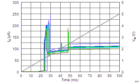
The REF31xx features a low quiescent current, which is extremely stable over changes in both temperature and supply. The typical room temperature quiescent current is 100 μA, and the maximum quiescent current over temperature is just 135 μA. The quiescent current typically changes less than 2 μA over the entire supply range, as shown in Figure 20.
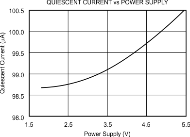 Figure 20. Supply Current vs Supply Voltage
Supply voltages below the specified levels can cause the REF31xx to momentarily draw currents greater than the typical quiescent current. This can be prevented by using a power supply with a fast rising edge and low output impedance.
8.3.2 Thermal Hysteresis
Thermal hysteresis for the REF31xx is defined as the change in output voltage after operating the device at 25°C, cycling the device through the specified temperature range, and returning to 25°C. It can be expressed as:

where
8.3.3 Temperature Drift
The REF31xx is designed to exhibit minimal drift error, defined as the change in output voltage over varying temperature. The drift is calculated using the box method, which is described in Equation 2:

The REF31xx features a typical drift coefficient of 5 ppm from 0°C to 70°C, the primary temperature range for many applications. For the industrial temperature range of –40°C to +125°C, the REF31xx family drift increases to a typical value of 10 ppm.
8.3.4 Noise Performance
Typical 0.1-Hz to 10-Hz voltage noise can be seen in Figure 21. The noise voltage of the REF31xx increases with output voltage and operating temperature. Additional filtering may be used to improve output noise levels, although take care to ensure the output impedance does not degrade the AC performance.
 Figure 21. 0.1-Hz to 10-Hz Noise
8.3.5 Long-Term Stability
Long-term stability refers to the change of the output voltage of a reference over a period of months or years. This effect lessens as time progresses, as is shown by the long-term stability curves. The typical drift value for the REF31xx is 70 ppm from 0 to 1000 hours. This parameter is characterized by measuring 30 units at regular intervals for a period of 1000 hours.
 Figure 22. REF3112 Long-Term Stability
8.3.6 Load Regulation
Load regulation is defined as the change in output voltage due to changes in load current. The load regulation of the REF31xx is measured using force and sense contacts as pictured in Figure 23. The force and sense lines reduce the impact of contact and trace resistance, resulting in accurate measurement of the load regulation contributed solely by the REF31xx. For applications requiring improved load regulation, force and sense lines must be used.
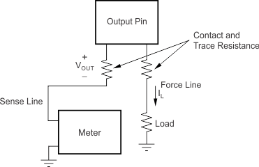 Figure 23. Accurate Load Regulation of REF31xx
8.4 Device Functional Modes
8.4.1 Negative Reference Voltage
For applications requiring a negative and positive reference voltage, the REF31xx and OPA703 can be used to provide a dual-supply reference from a ±5-V supply. Figure 24 shows the REF3125 used to provide a ±2.5-V supply reference voltage. The low drift performance of the REF31xx complement the low offset voltage and low drift of the OPA703 to provide an accurate solution for split-supply applications.
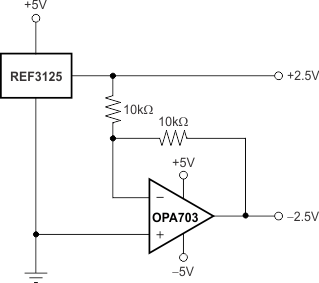 Figure 24. REF3125 Combined With OPA703 to Create Positive and Negative Reference Voltages
8.4.2 Data Acquisition
Data acquisition systems often require stable voltage references to maintain accuracy. The REF31xx family features stability and a wide range of voltages suitable for most microcontrollers and data converters. Figure 25, Figure 26, and Figure 27 show basic data acquisition systems.
 Figure 25. Basic Data Acquisition System 1
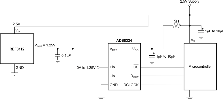 Figure 26. Basic Data Acquisition System 2
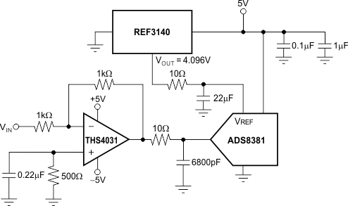 Figure 27. REF3140 Provides an Accurate Reference for Driving the ADS8381
9 Application and Implementation
NOTE
Information in the following applications sections is not part of the TI component specification, and TI does not warrant its accuracy or completeness. TI’s customers are responsible for determining suitability of components for their purposes. Customers should validate and test their design implementation to confirm system functionality.
9.1 Application Information
The REF31xx does not require a load capacitor and is stable with any capacitive load. Figure 28 shows typical connections required for operation of the REF31xx. TI recommends a supply bypass capacitor of 0.47 μF.
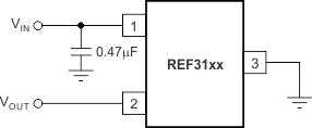 Figure 28. Typical Connections for Operating REF31xx
9.2 Typical Application
Figure 29 shows a low-power reference and conditioning circuit. This circuit attenuates and level-shifts a bipolar input voltage within the proper input range of a single-supply, low-power, 16-bit ΔΣ ADC, such as the one inside the MSP430 or other similar single-supply ADCs. Precision reference circuits are used to level-shift the input signal, provide the ADC reference voltage, and to create a well-regulated supply voltage for the low-power analog circuitry. A low-power, zero-drift, op-amp circuit is used to attenuate and level-shift the input signal.
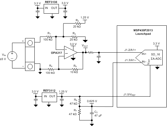 Figure 29. Low-Power Reference and Bipolar Voltage Conditioning Circuit for Low-Power ADCs
9.2.1 Design Requirements
- Supply Voltage: 3.3 V
- Maximum Input Voltage: ±6 V
- Specified Input Voltage: ±5 V
- ADC Reference Voltage: 1.25 V
The goal for this design is to accurately condition a ±5-V bipolar input voltage into a voltage suitable for conversion by a low-voltage ADC with a 1.25-V reference voltage, VREF, and an input voltage range of VREF / 2. The circuit should function with reduced performance over a wider input range of at least ±6 V to allow for easier protection of overvoltage conditions.
9.2.2 Detailed Design Procedure
Figure 29 depicts a simplified schematic for this design showing the MSP430 ADC inputs and full input conditioning circuitry. The ADC is configured for a bipolar measurement where final conversion result is the differential voltage between the voltage at the positive and negative ADC inputs. The bipolar, GND-referenced input signal must be level-shifted and attenuated by the op amp so that the output is biased to VREF/2 and has a differential voltage that is within the ±VREF/2 input range of the ADC.
9.2.3 Application Curves
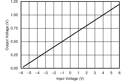 Figure 30. OPA317 Output Voltage vs Input Voltage
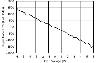 Figure 32. Output Code Error vs Input Voltage
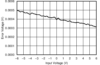 Figure 31. OPA317 Output Voltage Error vs Input Voltage
10 Power Supply Recommendations
The REF31xx family of references features an extremely low dropout voltage. With the exception of the REF3112, which has a minimum supply requirement of 1.8 V, these references can be operated with a supply of only 5 mV above the output voltage in an unloaded condition. For loaded conditions, a typical dropout voltage versus load is shown in the front page plot, Dropout Voltage vs Load Current. TI recommends a supply bypass capacitor greater than 0.47 μF.
