-
SNx4HC373 Octal Transparent D-Type Latches With 3-State Outputs
- 1
- 1 Features
- 2 Description
- 3 Pin Configuration and Functions
- 4 Specifications
- 5 Parameter Measurement Information
- 6 Detailed Description
- 7 Application and Implementation
- 8 Device and Documentation Support
- 9 Revision History
- 10Mechanical, Packaging, and Orderable Information
- IMPORTANT NOTICE
Package Options
Refer to the PDF data sheet for device specific package drawings
Mechanical Data (Package|Pins)
- W|20
- J|20
- FK|20
Thermal pad, mechanical data (Package|Pins)
Orderable Information
Data Sheet
SNx4HC373 Octal Transparent D-Type Latches With 3-State Outputs
1 Features
- Wide operating voltage range of 2V to 6V
- High-current 3-state true outputs can drive up to 15 LSTTL loads
- Low power consumption, 80µA max ICC
- Typical tpd = 13ns
- ±6mA output drive at 5V
- Low input current of 1µA max
- Eight high-current latches in a single package
- Full parallel access for loading
2 Description
These 8-bit latches feature 3-state outputs designed specifically for driving highly capacitive or relatively low-impedance loads. They are particularly suitable for implementing buffer registers, I/O ports, bidirectional bus drivers, and working registers.
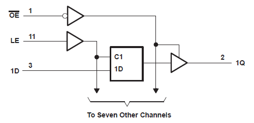
The eight latches of the ’HC373 devices are transparent D-type latches. While the latch-enable (LE) input is high, the Q outputs follow the data (D) inputs. When LE is taken low, the Q outputs are latched at the levels that were set up at the D inputs.
Device Information
| PART NUMBER | PACKAGE(1) | BODY SIZE(2) |
|---|---|---|
| SN74HC373 | DW (SOIC, 20) | 12.80 mm × 7.50 mm |
| DB (SSOP, 20) | 7.20 mm × 5.30 mm | |
| N (PDIP, 20) | 25.40 mm × 6.35 mm | |
| NS (SOP, 20) | 15.00 mm × 5.30 mm | |
| PW (TSSOP, 20) | 6.50 mm × 4.40 mm | |
| SN54HC373 | J (CDIP, 20) | 26.92 mm × 6.92 mm |
| FK (LCCC, 20) | 8.89 mm × 8.45 mm | |
| W (CFP, 20) | 13.72 mm × 6.92 mm |
(1) For more information, see Section 10.
(2) The body size (length × width) is a nominal value and does not include
pins.
 Logic Diagram (Positive Logic)
3 Pin Configuration and Functions
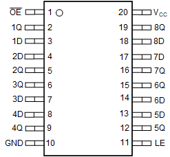
 J, W, FK, DB, DW, N, NS, or PW
package
J, W, FK, DB, DW, N, NS, or PW
package20--Pin CDIP, CFP, LCCC, SSOP, SOIC, PDIP, SO, or TSSOP
Top View
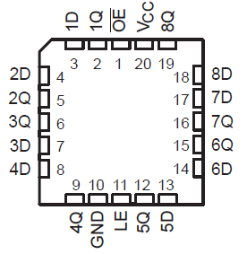
 FK package
20-Pin LCCC
Top View
Table 3-1 Pin Functions
| PIN | TYPE1 | DESCRIPTION | |
|---|---|---|---|
| NAME | NO. | ||
| OE | 1 | Input | Output enable, active low |
| 1Q | 2 | Output | Output for channel 1 |
| 1D | 3 | Input | Input for channel 1 |
| 2D | 4 | Input | Input for channel 2 |
| 2Q | 5 | Output | Output for channel 2 |
| 3Q | 6 | Output | Output for channel 3 |
| 3D | 7 | Input | Input for channel 3 |
| 4D | 8 | Input | Input for channel 4 |
| 4Q | 9 | Output | Output for channel 4 |
| GND | 10 | — | Ground |
| LE | 11 | Input | Latch enable |
| 5Q | 12 | Output | Output for channel 5 |
| 5D | 13 | Input | Input for channel 5 |
| 6D | 14 | Input | Input for channel 6 |
| 6Q | 15 | Output | Output for channel 6 |
| 7Q | 16 | Output | Output for channel 7 |
| 7D | 17 | Input | Input for channel 7 |
| 8D | 18 | Input | Input for channel 8 |
| 8Q | 19 | Output | Output for channel 8 |
| VCC | 20 | — | Positive supply |
- I = input, O = output, P = power, FB = feedback, GND = ground, N/A = not applicable