SCDS112E march 2001 – september 2023 SN74TVC3306
PRODUCTION DATA
- 1
- 1 Features
- 2 Applications
- 3 Description
- 4 Revision History
- 5 Pin Configuration and Functions
-
6 Specifications
- 6.1 Absolute Maximum Ratings
- 6.2 ESD Ratings
- 6.3 Recommended Operating Conditions
- 6.4 Thermal Information
- 6.5 Electrical Characteristics
- 6.6 Switching Characteristics (AC, VGATE = 3.3 V, Translating Down)
- 6.7 Switching Characteristics (AC, VGATE = 2.5 V, Translating Down)
- 6.8 Switching Characteristics (AC, VGATE = 3.3 V, Translating Up)
- 6.9 Switching Characteristics (AC, VGATE = 2.5 V, Translating Up)
- 6.10 Typical Characteristics
- 7 Parameter Measurement Information
- 8 Detailed Description
- 9 Application and Implementation
- 10Device and Documentation Support
- 11Mechanical, Packaging, and Orderable Information
Package Options
Refer to the PDF data sheet for device specific package drawings
Mechanical Data (Package|Pins)
- DCU|8
- DCT|8
Thermal pad, mechanical data (Package|Pins)
Orderable Information
3 Description
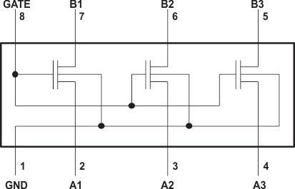
The SN74TVC3306 device provides three parallel NMOS pass transistors with a common unbuffered gate. The low on-state resistance of the switch allows connections to be made with minimal propagation delay.
The device can be used as a dual switch, with the gates cascaded together to a reference transistor. The low-voltage side of each pass transistor is limited to a voltage set by the reference transistor. This is done to protect components with inputs that are sensitive to high-state voltage-level overshoots.
Package
Information
| PART NUMBER | PACKAGE(1) | PACAKGE SIZE(2) |
|---|---|---|
| SN74TVC3306 | DCT (SSOP, 8) | 2.95 mm × 4 mm |
| DCU (VSSOP, 8) | 2 mm × 3.1 mm |
(1) For all available packages, see the orderable addendum at the end of the data
sheet.
(2) The package size (length × width) is a nominal value and includes
pins, where applicable.

The SN74TVC3306 device has bidirectional capability across many
voltage levels. The voltage levels documented in this data sheet are
examples.
Simplified Schematic