SLLS038C October 1980 – April 2024 SN75172
PRODUCTION DATA
- 1
- 1 Features
- 2 Applications
- 3 Description
- 4 Pin Configuration and Functions
- 5 Specifications
- 6 Parameter Measurement Information
- 7 Detailed Description
- 8 Application and Implementation
- 9 Device and Documentation Support
- 10Revision History
- 11Mechanical, Packaging, and Orderable Information
Package Options
Refer to the PDF data sheet for device specific package drawings
Mechanical Data (Package|Pins)
- N|16
- DW|20
Thermal pad, mechanical data (Package|Pins)
Orderable Information
8.1 Application Information
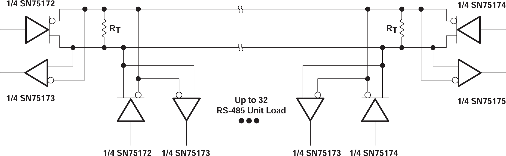
A. The line length should be terminated at both ends in its characteristic
impedance (RT = ZO). Stub lengths off the main line should
be kept as short as possible.