SLASFC6 August 2024 TAS2120
ADVANCE INFORMATION
- 1
- 1 Features
- 2 Applications
- 3 Description
- 4 Pin Configuration and Functions
- 5 Specifications
-
6 Detailed Description
- 6.1 Overview
- 6.2 Functional Block Diagram
- 6.3 Device Functional Modes
- 6.4 Feature Description
- 6.5 Programming
- 7 Application and Implementation
- 8 Power Supply Recommendations
- 9 Layout
- 10Device and Documentation Support
- 11Revision History
- 12Mechanical, Packaging, and Orderable Information
Package Options
Mechanical Data (Package|Pins)
- RBG|26
Thermal pad, mechanical data (Package|Pins)
Orderable Information
6.4.2.4.1 Voltage Limiter and Clipping protection
The supply tracking limiter can be configured using LIM_MODE[1:0] register. In the VBAT voltage mode, the limiter tracks the VBAT supply voltage for voltage limiter and in PVDD voltage mode, the limiter tracks the PVDD voltage for external PVDD mode of use case.
| LIM_MODE[1:0] | Configuration |
|---|---|
| 00 (default) | Disabled |
| 01 | VBAT voltage based limiter |
| 10 | PVDD voltage based limiter |
| 11 | Reserved |
| SUPPLY_HEADROOM_LIM_MODE | Configuration |
|---|---|
| 0(default) | Disabled |
| 1 | Enabled. Limiter threshold is dynamically changed based as a fixed percentage of monitored supply voltage. |
When SUPPLY_HEADROOM_LIM_MODE is set high, the limiter sets the threshold as a fixed percentage of the monitored supply voltage. The limiter begins reducing gain when the output signal level is greater than the threshold configured. For eg, if voltage limiting is desired to be 10% below the supply voltage, then LIM_SLOPE[23:0] is configured as 0.9 and the threshold is calculated as monitored supply voltage multiplied by 1.1. Similarly if the LIM_SLOPE[23:0] is configured at > 1.0, the limiter threshold is set at higher than the supply voltage, and a small amount of controlled clipping occurs.
 Figure 6-5 Limiter with dynamic
supply headroom
Figure 6-5 Limiter with dynamic
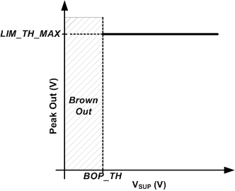
supply headroomWhen SUPPLY_HEADROOM_LIM_MODE is set low, the limiter begins reducing gain when the output signal level is greater than the limiter threshold. The limiter can be configured to track selected supply below a programmable inflection point with a minimum threshold value. Figure 6-6below shows the limiter configured to limit to a constant level regardless of the selected supply level. To achieve this behavior, set the limiter maximum threshold to the desired level using LIM_TH_MAX[23:0]. Set the limiter inflection point using LIM_INF_PT[23:0] below the minimum allowable supply setting. The limiter minimum threshold register LIM_TH_MIN[23:0] does not impact limiter behavior in this use case.
 Figure 6-6 Limiter
with Fixed Threshold
Figure 6-6 Limiter
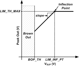
with Fixed ThresholdFigure 6-7 shows how to configure the limiter to track selected supply below a threshold without a minimum threshold. Set the LIM_TH_MAX[23:0] register to the desired threshold and LIM_INF_PT[23:0] register to the desired inflection point where the limiter begins to reduce the threshold with the selected supply. The LIM_SLOPE[23:0] register bits can be used to change the slope of the limiter tracking the supply voltage in V/V. For example, a slope value of 1 V/V reduces the limiter threshold 1 V for every 1 V of drop in the supply voltage. Program the LIM_TH_MIN[23:0] below the minimum of the selected supply to prevent the limiter from having a minimum threshold reduction when tracking the selected supply.
 Figure 6-7 Limiter
with Inflection Point
Figure 6-7 Limiter
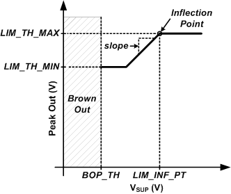
with Inflection PointTo achieve a limiter that tracks the selected supply below a threshold, configure the limiter as explained in the previous example, except program the LIM_TH_MIN[23:0] register to the desired minimum threshold. This is shown in Figure 6-8 below.
 Figure 6-8 Limiter
with Inflection Point and Minimum Threshold
Figure 6-8 Limiter
with Inflection Point and Minimum ThresholdThe limiter has a configurable attack rate (dB/Sample), hold time ( no of samples) and release rate (db/Sample), which are available via the LIM_ATK_RATE[23:0], LIM_HLD_COUNT[23:0], LIM_RLS_RATE[23:0] register bits.