SCPS290A April 2024 – June 2024 TCAL6416R
PRODUCTION DATA
- 1
- 1 Features
- 2 Applications
- 3 Description
- 4 Pin Configuration and Functions
- 5 Specifications
- 6 Parameter Measurement Information
- 7 Detailed Description
- 8 Application and Implementation
- 9 Device and Documentation Support
- 10Revision History
- 11Mechanical, Packaging, and Orderable Information
Package Options
Refer to the PDF data sheet for device specific package drawings
Mechanical Data (Package|Pins)
- DTO|24
Thermal pad, mechanical data (Package|Pins)
Orderable Information
7.6.4.2 Reads
The bus controller must first send the TCAL6416R address with the LSB set to a logic 0 (see Figure 7-7 for device address). The command byte is sent after the address and determines which register is accessed.
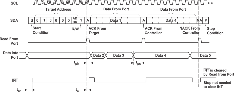
After a restart, the device address is sent again, but this time the least significant bit is set to a logic 1. Data from the register defined by the command byte is sent by the TCAL6416R (see Figure 7-11 and Figure 7-12). Data is clocked into the register on the rising edge of the ACK clock pulse. After the first byte is read, additional bytes may be read, but the data now reflects the information in the other register in the pair. For example, if Input Port 1 is read, the next byte read is Input Port 0. There is no limit on the number of data bytes received in one read transmission, but on the final byte received, the bus controller must not acknowledge the data. After a subsequent restart, the command byte contains the value of the next register to be read in the pair. For example, if Input Port 1 was read last before the restart, then the register that is read after the restart is the Input Port 0.
 Figure 7-11 Read From
Register