SBOS758F April 2016 – June 2024 THS6212
PRODUCTION DATA
- 1
- 1 Features
- 2 Applications
- 3 Description
- 4 Pin Configuration and Functions
- 5 Specifications
- 6 Detailed Description
- 7 Application and Implementation
- 8 Device and Documentation Support
- 9 Revision History
- 10Mechanical, Packaging, and Orderable Information
Package Options
Refer to the PDF data sheet for device specific package drawings
Mechanical Data (Package|Pins)
- RHF|24
Thermal pad, mechanical data (Package|Pins)
Orderable Information
6.3.4 Differential Noise Performance
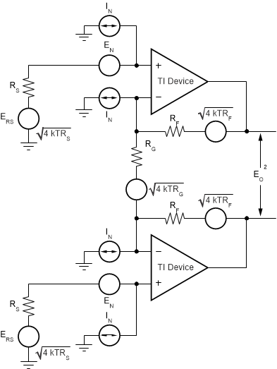
The THS6212 is designed to be used as a differential driver in high-performance applications. Therefore, analyzing the noise in such a configuration is important. Figure 6-3 shows the op amp noise model for the differential configuration.
 Figure 6-3 Differential Op Amp Noise Analysis Model
As a reminder, the differential gain is expressed in Equation 1:

The output noise can be expressed as shown in Equation 2:

Dividing this expression by the differential noise gain [GD = (1 + 2RF / RG)] gives the equivalent input-referred spot noise voltage at the noninverting input, as shown in Equation 3.

Evaluating these equations for the THS6212 circuit and component values of Figure 7-1 with RS = 50 Ω, gives a total output spot noise voltage of 53.3 nV/√Hz and a total equivalent input spot noise voltage of 6.5 nV/√Hz.
To minimize the output noise as a result of the noninverting input bias current noise, keep the noninverting source impedance as low as possible.