SLLS177I March 1994 – March 2021 TL16C550C
PRODUCTION DATA
- 1 Features
- 2 Description
- 3 Revision History
- 4 Pin Configuration and Functions
-
5 Specifications
- 5.1 Absolute Maximum Ratings
- 5.2 Recommended Operating Conditions (Low Voltage - 3.3 nominal)
- 5.3 Recommended Operating Conditions (Standard Voltage - 5 V nominal)
- 5.4 Thermal Information
- 5.5 Electrical Characteristics (Low Voltage - 3.3 V nominal)
- 5.6 Electrical Characteristics (Standard Voltage - 5 V nominal)
- 5.7 System Timing Requirements
- 5.8 System Switching Characteristics
- 5.9 Baud Generator Switching Characteristics
- 5.10 Receiver Switching Characteristics
- 5.11 Transmitter Switching Characteristics
- 5.12 Modem Control Switching Characteristics
- 6 Parameter Measurement Information
-
7 Detailed Description
- 7.1 Autoflow Control (see Figure 1-1)
- 7.2 Auto-RTS (see Figure 1-1)
- 7.3 Auto-CTS (see Figure 1-1)
- 7.4 Enabling Autoflow Control and Auto-CTS
- 7.5 Auto-CTS and Auto-RTS Functional Timing
- 7.6 Functional Block Diagram
- 7.7
Principles of Operation
- 7.7.1 Accessible Registers
- 7.7.2 FIFO Control Register (FCR)
- 7.7.3 FIFO Interrupt Mode Operation
- 7.7.4 FIFO Polled Mode Operation
- 7.7.5 Interrupt Enable Register (IER)
- 7.7.6 Interrupt Identification Register (IIR)
- 7.7.7 Line Control Register (LCR)
- 7.7.8 Line Status Register (LSR)
- 7.7.9 Modem Control Register (MCR)
- 7.7.10 Modem Status Register (MSR)
- 7.7.11 Programming Baud Generator
- 7.7.12 Receiver Buffet Register (RBR)
- 7.7.13 Scratch Register
- 7.7.14 Transmitter Holding Register (THR)
- 8 Application Information
- 9 Device and Documentation Support
- 10Mechanical, Packaging, and Orderable Information
Package Options
Mechanical Data (Package|Pins)
Thermal pad, mechanical data (Package|Pins)
Orderable Information
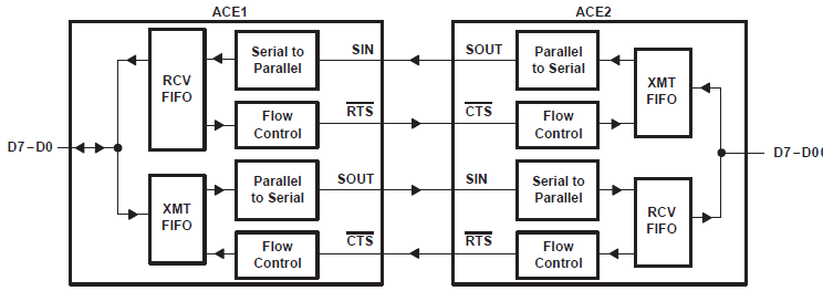
7.1 Autoflow Control (see Figure 7-1)
Autoflow control is comprised of auto-CTS and auto-RTS. With auto-CTS, the CTS input must be active before the transmitter FIFO can emit data. With auto-RTS, RTS becomes active when the receiver needs more data and notifies the sending serial device. When RTS is connected to CTS, data transmission does not occur unless the receiver FIFO has space for the data; thus, overrun errors are eliminated using ACE1 and ACE2 from a TLC16C550C with the autoflow control enabled. If not, overrun errors occur when the transmit data rate exceeds the receiver FIFO read latency.
 Figure 7-1 Autoflow Control (Auto-RTS and
Auto-CTS) Example