SLLSF10 December 2019 TL16C750E
PRODUCTION DATA.
- 1 Features
- 2 Applications
- 3 Description
- 4 Revision History
- 5 Description (continued)
- 6 Pin Configuration and Functions
- 7 Specifications
- 8 Parameter Measurement Information
-
9 Detailed Description
- 9.1 Overview
- 9.2 Functional Block Diagrams
- 9.3
Feature Description
- 9.3.1 UART Modes
- 9.3.2 Trigger Levels
- 9.3.3 Hardware Flow Control
- 9.3.4 Auto-RTS
- 9.3.5 Auto-CTS
- 9.3.6 Software Flow Control
- 9.3.7 Software Flow Control Example
- 9.3.8 Reset
- 9.3.9 Interrupts
- 9.3.10 Interrupt Mode Operation
- 9.3.11 Polled Mode Operation
- 9.3.12 Break and Timeout Conditions
- 9.3.13 Programmable Baud Rate Generator with Fractional Divisor
- 9.3.14 Fractional Divisor
- 9.4 Device Functional Modes
- 9.5
Register Maps
- 9.5.1 Registers Operations
- 9.5.2 Receiver Holding Register (RHR)
- 9.5.3 Transmit Holding Register (THR)
- 9.5.4 FIFO Control Register (FCR)
- 9.5.5 Line Control Register (LCR)
- 9.5.6 Line Status Register (LSR)
- 9.5.7 Modem Control Register (MCR)
- 9.5.8 Modem Status Register (MSR)
- 9.5.9 Interrupt Enable Register (IER)
- 9.5.10 Interrupt Identification Register (IIR)
- 9.5.11 Enhanced Feature Register (EFR)
- 9.5.12 Divisor Latches (DLL, DLH, DLF)
- 9.5.13 Transmission Control Register (TCR)
- 9.5.14 Trigger Level Register (TLR)
- 9.5.15 FIFO Ready Register
- 9.5.16 Alternate Function Register (AFR)
- 9.5.17 RS-485 Mode
- 9.5.18 IrDA Overview
- 9.5.19 IrDA Encoder Function
- 10Application and Implementation
- 11Power Supply Recommendations
- 12Layout
- 13Device and Documentation Support
- 14Mechanical, Packaging, and Orderable Information
Package Options
Mechanical Data (Package|Pins)
- PFB|48
Thermal pad, mechanical data (Package|Pins)
Orderable Information
3 Description
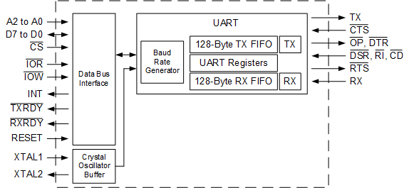
The TL16C750E is a single universal asynchronous receiver transmitter (UART) with 128-byte FIFOs, fractional baud rate support, automatic hardware, software flow control and data rates up to 6 Mbps. The device offers enhanced features such as fractional baud rate and a transmission character control register (TCR) that stores received FIFO threshold level to start or stop transmission during hardware and software flow control automatically without intervention from the CPU.
With the FIFO RDY register, the software gets the status of TXRDY or RXRDY, saving extra GPIO usage. On-chip status registers provide the user with error indications, operational status, and modem interface control. System interrupts may be tailored to meet user requirements. An internal loop-back capability allows onboard diagnostics. The TL16C750E incorporates the functionality of UART, the UART having its own register set and FIFO.
This version includes the Alternate Function Register (AFR) and this is used to enable some extra functionality beyond the capabilities of the TL16C750 version. One addition is the IrDA mode, which supports Standard IrDA (SIR) mode with baud rates from 2400 to 115.2 kbps. The third addition is support for RS-485 bus drivers or transceivers by providing an output pin (DTRx) per channel, which is timed to keep the RS-485 driver enabled as long as transmit data is pending.
Device Information(1)
| PART NUMBER | PACKAGE | BODY SIZE (NOM) |
|---|---|---|
| TL16C750E | TQFP (48) | 7.00 mm × 7.00 mm |
- For all available packages, see the orderable addendum at the end of the data sheet.
Block Diagram
