-
TL494 Pulse-Width-Modulation Control Circuits
- 1 Features
- 2 Applications
- 3 Description
- 4 Simplified Block Diagram
- 5 Revision History
- 6 Pin Configuration and Functions
-
7 Specifications
- 7.1 Absolute Maximum Ratings
- 7.2 ESD Ratings
- 7.3 Recommended Operating Conditions
- 7.4 Thermal Information
- 7.5 Electrical Characteristics, Reference Section
- 7.6 Electrical Characteristics, Oscillator Section
- 7.7 Electrical Characteristics, Error-Amplifier Section
- 7.8 Electrical Characteristics, Output Section
- 7.9 Electrical Characteristics, Dead-Time Control Section
- 7.10 Electrical Characteristics, PWM Comparator Section
- 7.11 Electrical Characteristics, Total Device
- 7.12 Switching Characteristics
- 7.13 Typical Characteristics
- 8 Parameter Measurement Information
- 9 Detailed Description
- 10Application and Implementation
- 11Power Supply Recommendations
- 12Layout
- 13Device and Documentation Support
- 14Mechanical, Packaging, and Orderable Information
- IMPORTANT NOTICE
Package Options
Mechanical Data (Package|Pins)
Thermal pad, mechanical data (Package|Pins)
Orderable Information
TL494 Pulse-Width-Modulation Control Circuits
1 Features
- Complete PWM Power-Control Circuitry
- Uncommitted Outputs for 200-mA Sink or
Source Current - Output Control Selects Single-Ended or
Push-Pull Operation - Internal Circuitry Prohibits Double Pulse at
Either Output - Variable Dead Time Provides Control Over
Total Range - Internal Regulator Provides a Stable 5-V Reference Supply With 5% Tolerance
- Circuit Architecture Allows Easy Synchronization
2 Applications
- Desktop PCs
- Microwave Ovens
- Power Supplies: AC/DC, Isolated, With or Without PFC
- Server PSUs
- Solar Micro-Inverters
- Washing Machines: Low-End and High-End
- E-Bikes
- Power: Telecom/Server AC/DC
Supplies:
Dual Controller: Analog - Smoke Detectors
- Solar Power Inverters
3 Description
The TL494 device incorporates all the functions required in the construction of a pulse-width-modulation (PWM) control circuit on a single chip. Designed primarily for power-supply control, this device offers the flexibility to tailor the power-supply control circuitry to a specific application.
The TL494 device contains two error amplifiers, an on-chip adjustable oscillator, a dead-time control (DTC) comparator, a pulse-steering control flip-flop, a 5-V, 5%-precision regulator, and output-control circuits.
The error amplifiers exhibit a common-mode voltage range from –0.3 V to VCC – 2 V. The dead-time control comparator has a fixed offset that provides approximately 5% dead time. The on-chip oscillator can be bypassed by terminating RT to the reference output and providing a sawtooth input to CT, or it can drive the common circuits in synchronous multiple-rail power supplies.
The uncommitted output transistors provide either common-emitter or emitter-follower output capability. The TL494 device provides for push-pull or single-ended output operation, which can be selected through the output-control function. The architecture of this device prohibits the possibility of either output being pulsed twice during push-pull operation.
The TL494 device is characterized for operation from 0°C to 70°C. The TL494I device is characterized for operation from –40°C to 85°C.
| PART NUMBER | PACKAGE (PIN) | BODY SIZE |
|---|---|---|
| TL494 | SOIC (16) | 9.90 mm × 3.91 mm |
| PDIP (16) | 19.30 mm × 6.35 mm | |
| SOP (16) | 10.30 mm × 5.30 mm | |
| TSSOP (16) | 5.00 mm × 4.40 mm |
4 Simplified Block Diagram

5 Revision History
Changes from Revision H (March 2017) to Revision I (July 2022)
- Updated the numbering format for tables, figures, and cross-references throughout the documentGo
Changes from Revision G (January 2015) to Revision H (March 2017)
Changes from Revision F (January 2014) to Revision G (January 2015)
- Added Applications, Device Information table, Pin Functions table, ESD Ratings table, Thermal Information table, , Feature Description section, Device Functional Modes, Application and Implementation section, Power Supply Recommendations section, Layout section, Device and Documentation Support section, and Mechanical, Packaging, and Orderable Information section.Go
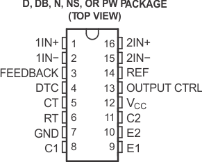
6 Pin Configuration and Functions

| PIN | TYPE | DESCRIPTION | |
|---|---|---|---|
| NAME | NO. | ||
| 1IN+ | 1 | I | Noninverting input to error amplifier 1 |
| 1IN- | 2 | I | Inverting input to error amplifier 1 |
| 2IN+ | 16 | I | Noninverting input to error amplifier 2 |
| 2IN- | 15 | I | Inverting input to error amplifier 2 |
| C1 | 8 | O | Collector terminal of BJT output 1 |
| C2 | 11 | O | Collector terminal of BJT output 2 |
| CT | 5 | — | Capacitor terminal used to set oscillator frequency |
| DTC | 4 | I | Dead-time control comparator input |
| E1 | 9 | O | Emitter terminal of BJT output 1 |
| E2 | 10 | O | Emitter terminal of BJT output 2 |
| FEEDBACK | 3 | I | Input pin for feedback |
| GND | 7 | — | Ground |
| OUTPUT CTRL | 13 | I | Selects single-ended/parallel output or push-pull operation |
| REF | 14 | O | 5-V reference regulator output |
| RT | 6 | — | Resistor terminal used to set oscillator frequency |
| VCC | 12 | — | Positive Supply |