SLDS156B March 2009 – July 2015 TLC59108
PRODUCTION DATA.
- 1 Features
- 2 Applications
- 3 Description
- 4 Revision History
- 5 Description (continued)
- 6 Pin Configuration and Functions
- 7 Specifications
- 8 Parameter Measurement Information
-
9 Detailed Description
- 9.1 Overview
- 9.2 Functional Block Diagram
- 9.3 Feature Description
- 9.4 Device Functional Modes
- 9.5 Programming
- 9.6
Register Maps
- 9.6.1
Register Descriptions
- 9.6.1.1 Mode Register 1 (MODE1)
- 9.6.1.2 Mode Register 2 (MODE2)
- 9.6.1.3 Brightness Control Registers 0 to 7 (PWM0 to PWM7)
- 9.6.1.4 Group Duty Cycle Control Register (GRPPWM)
- 9.6.1.5 Group Frequency Register (GRPFREQ)
- 9.6.1.6 LED Driver Output State Registers (LEDOUT0, LEDOUT1)
- 9.6.1.7 I2C Bus Subaddress Registers 1 to 3 (SUBADR1 to SUBADR3)
- 9.6.1.8 LED All Call I2C Bus Address Register (ALLCALLADR)
- 9.6.1.9 Output Gain Control Register (IREF)
- 9.6.1.10 Error Flags Registers (EFLAG)
- 9.6.1
Register Descriptions
- 10Application and Implementation
- 11Power Supply Recommendations
- 12Layout
- 13Device and Documentation Support
- 14Mechanical, Packaging, and Orderable Information
Package Options
Mechanical Data (Package|Pins)
Thermal pad, mechanical data (Package|Pins)
- RGY|20
Orderable Information
10 Application and Implementation
NOTE
Information in the following applications sections is not part of the TI component specification, and TI does not warrant its accuracy or completeness. TI’s customers are responsible for determining suitability of components for their purposes. Customers should validate and test their design implementation to confirm system functionality.
10.1 Application Information
10.1.1 Driver Output
10.1.1.1 Constant Current Output
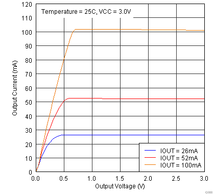
In LED display applications, TLC59108 provides nearly no current variations from channel to channel and from device to device. While IOUT ≤ 100 mA, the maximum current skew between channels is less than ±3% and less than ±6% between devices.
10.1.1.2 Adjusting Output Current
TLC59108 scales up the reference current (Iref) set by the external resistor (Rext) to sink the output current (Iout) at each output port. The following formulas can be used to calculate the target output current IOUT,target in the saturation region:
Where Rext is the resistance of the external resistor connected to the REXT terminal, and VREXT is the voltage of REXT, which is controlled by the programmable voltage gain (VG), which is defined by the Configuration Code. The Current Multiplier (CM) determines that the ratio IOUT,target/Iref is 15 or 5. After power on, the default value of VG is 127/128 = 0.992, and the default value of CM is 1, so that the ratio IOUT,target/Iref = 15. Based on the default VG and CM.
10.1.2 TLC59108 and TLC59108F Differences
The TLC59108 and TLC59108F are similar devices with the difference being the output structure. The TLC59108 has 8 constant-current outputs while the TLC59108F has 8 open drain outputs. The REXT is used to program the current on the TLC59108 for all channels. The in-line resistors on the OUT pins are used in conjunction with the VLED to set the currents on each TLC59108F channel. Since the resistors are unique for each output, the currents can be set by output by changing the resistor value.
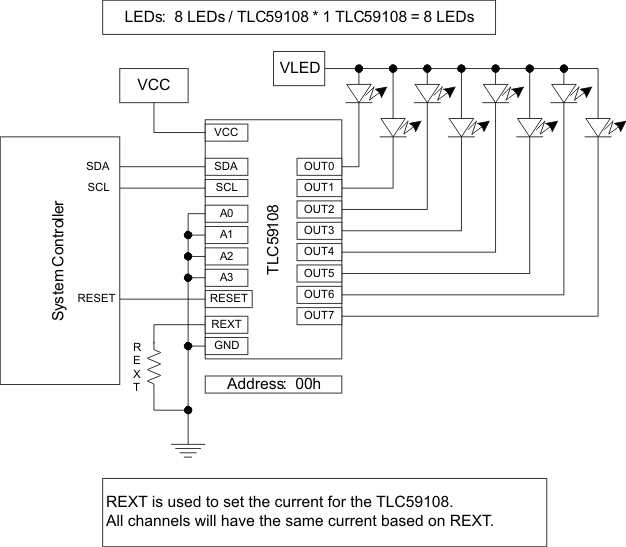 Figure 22. TLC59108 One Driver
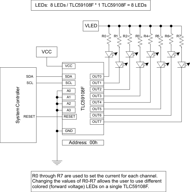 Figure 23. TLC59108F One Driver
10.2 Typical Application
10.2.1 Parallel Outputs
The TLC59108 outputs can be wired in parallel to increase the current per LED string.
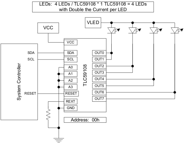 Figure 24. Parallel Channels
10.2.1.1 Design Requirements
Set the LED current to 50 mA while the IREF register is at the default value (CG = 0.992).
10.2.1.2 Detailed Design Procedure
The goal of this design is to set the LED current to 50 mA. Because there are two outputs in parallel, the LED current should actually be set to 25 mA. With the IREF register at the default value:
Using this equation, the appropriate REXT is calculated to be 750 Ω.
10.2.1.3 Application Curve
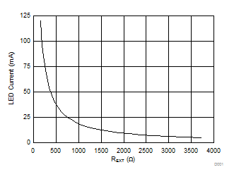 Figure 25. LED Current vs REXTResistor
10.2.2 Multiple Devices
This drawing is an example of using the TLC59108 in a system requiring up to 48 LED strings. The TLC59108 drivers share a single I2C bus. The address pins are set high or low to enable the drivers to be independently accessed (all can be written in parallel through the ALLCALLADR function). The REXT pins are each tied to ground through a programming resistor. Since the devices are independent the resistors on the REXT pins can be of different values allowing multi-color displays.
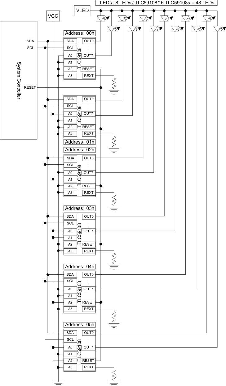 Figure 26. Six Drivers
