-
TLV62095 4-A High Efficiency Step Down Converter with DCS-Control™
- 1 Features
- 2 Applications
- 3 Description
- 4 Revision History
- 5 Pin Configuration and Functions
- 6 Specifications
- 7 Detailed Description
- 8 Application and Implementation
- 9 Power Supply Recommendations
- 10Layout
- 11Device and Documentation Support
- 12Mechanical, Packaging, and Orderable Information
- IMPORTANT NOTICE
Package Options
Mechanical Data (Package|Pins)
- RGT|16
Thermal pad, mechanical data (Package|Pins)
- RGT|16
Orderable Information
TLV62095 4-A High Efficiency Step Down Converter with DCS-Control™
1 Features
- 2.5 V to 5.5 V Input Voltage Range
- DCS-Control™
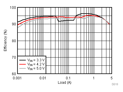
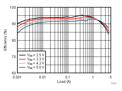
- Up to 95% Efficiency
- Power Save Mode
- 20 µA Operating Quiescent Current
- 100% Duty Cycle for Lowest Dropout
- 1.4 MHz Typical Switching Frequency
- 0.8 V to VIN Adjustable Output Voltage
- Output Discharge Function
- Adjustable Soft Startup
- Hiccup Short Circuit Protection
- Output Voltage Tracking
- Pin-to-Pin Compatible with TLV62090 and TPS62095
- For Improved Feature Set, See TPS62095
- Create a Custom Design Using the TLV62095 With the WEBENCH® Power Designer
2 Applications
- TV, STB, Computers
- Solid State Drives (SSD)
- Hard Disk Drives (HDD)
- Battery Powered Applications
3 Description
The TLV62095 device is a high frequency synchronous step-down converter optimized for small solution size, high efficiency and suitable for battery powered applications. To maximize efficiency, the converter operates in PWM mode with a nominal switching frequency of 1.4MHz and it automatically enters Power Save Mode operation at light load currents. When used in distributed power supplies and point of load regulation, the device allows voltage tracking to other voltage rails and tolerates output capacitors ranging from 10 µF to 150 µF and beyond. Using the DCS-Control™ topology, the device achieves excellent load transient performance and accurate output voltage regulation.
The output voltage start-up ramp is controlled by the soft startup pin, which allows operation as either a standalone power supply or in tracking configurations. Power sequencing is also possible by configuring the EN and PG pins. In Power Save Mode, the device operates with typically 20-µA quiescent current. Power Save Mode is entered automatically and seamlessly maintaining high efficiency over the entire load current range.
The device is available in a 3 mm x 3 mm 16-pin VQFN package.
Device Information(1)
| PART NUMBER | PACKAGE | BODY SIZE (NOM) |
|---|---|---|
| TLV62095 | VQFN (16) | 3.00 mm × 3.00 mm |
1.8 V Output Application
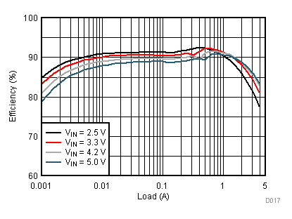
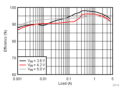
1.8 V Output Application Efficiency
5 Pin Configuration and Functions

Pin Functions
| PIN | DESCRIPTION | |
|---|---|---|
| NAME | NO. | |
| SW | 1, 2 | Switch pin of the power stage. |
| DEF | 3 | This pin is used for internal logic and needs to be pulled high. This pin must be connected to the AVIN pin. |
| PG | 4 | Power good open drain output. A pull up resistor can not be connected to any voltage higher than the input voltage. |
| FB | 5 | Feedback pin for regulating the output voltage. |
| AGND | 6 | Analog ground. |
| CP | 7 | Internal charge pump's flying capacitor. Connect a 10nF capacitor between CP and CN. |
| CN | 8 | Internal charge pump's flying capacitor. Connect a 10nF capacitor between CP and CN. |
| SS | 9 | Soft-start control pin. A capacitor is connected to this pin and sets the soft startup time. Leaving this pin floating sets the minimum start-up time. |
| AVIN | 10 | Analog supply input voltage pin. |
| PVIN | 11,12 | Power supply input voltage pin. |
| EN | 13 | Enable pin. This pin has an active pull down resistor of typically 400kΩ, which is active when EN is low. To enable the device, this pin needs to be pulled high. Pulling this pin low disables the device. |
| PGND | 14,15 | Power ground. |
| VOS | 16 | Output voltage sense pin. This pin must be directly connected to the output voltage. |
| Exposed Thermal Pad | The exposed thermal pad must be connected to AGND. It must be soldered for mechanical reliability. | |
6 Specifications
6.1 Absolute Maximum Ratings(1)
| MIN | MAX | UNIT | ||
|---|---|---|---|---|
| Voltage at pins(2) | PVIN, AVIN, FB, SS, EN, DEF, VOS | – 0.3 | 7 | V |
| SW (DC), PG | – 0.3 | VIN+0.3 | ||
| SW (AC, less than 10 ns)(3) | – 3.0 | 10 | ||
| CN, CP | – 0.3 | VIN+7.0 | ||
| Sink current | PG | 1.0 | mA | |
| Operating junction temperature range, TJ | – 40 | 150 | °C | |
| Storage temperature, Tstg | – 65 | 150 | °C | |
6.2 ESD Ratings
| MAX | UNIT | |||
|---|---|---|---|---|
| V(ESD) | Electrostatic discharge | Human body model (HBM), per ANSI/ESDA/JEDEC JS-001, all pins(1) | ±2000 | V |
| Charged device model (CDM), per JEDEC specification JESD22-C101, all pins(2) | ±500 | |||
6.3 Recommend Operating Conditions
| MIN | MAX | UNIT | ||
|---|---|---|---|---|
| VIN | Input voltage range | 2.5 | 5.5 | V |
| TJ | Operating junction temperature | -40 | 125 | °C |
6.4 Thermal Information
| THERMAL METRIC(1) | TLV62095 | UNIT | |
|---|---|---|---|
| VQFN (16 PINS) | |||
| RθJA | Junction-to-ambient thermal resistance | 47 | °C/W |
| RθJC(top) | Junction-to-case (top) thermal resistance | 60 | |
| RθJB | Junction-to-board thermal resistance | 20 | |
| ψJT | Junction-to-top characterization parameter | 1.5 | |
| ψJB | Junction-to-board characterization parameter | 20 | |
| RθJC(bot) | Junction-to-case (bottom) thermal resistance | 5.3 | |
6.5 Electrical Characteristics
VIN = 3.6V and TJ = 25°C (unless otherwise noted)| PARAMETER | TEST CONDITIONS | MIN | TYP | MAX | UNIT | |
|---|---|---|---|---|---|---|
| SUPPLY | ||||||
| VIN | Input voltage range | 2.5 | 5.5 | V | ||
| IQ | Quiescent current into PVIN and AVIN | EN = High, Not switching, FB = FB +5% | 20 | µA | ||
| ISD | Shutdown current Into PVIN and AVIN | EN = Low | 0.6 | µA | ||
| VUVLO | Undervoltage lockout threshold | VIN falling | 2.1 | 2.2 | 2.3 | V |
| Undervoltage lockout hysteresis | 200 | mV | ||||
| TSD | Thermal shutdown | Temperature rising | 150 | ºC | ||
| Thermal shutdown hysteresis | 20 | ºC | ||||
| CONTROL SIGNAL EN | ||||||
| VH | High level input voltage | VIN = 2.5 V to 5.5 V | 1 | 0.65 | V | |
| VL | Low level input voltage | VIN = 2.5 V to 5.5 V | 0.60 | 0.4 | V | |
| Ilkg | Input leakage current | EN = GND or VIN | 10 | 100 | nA | |
| RPD | Pull down resistance | EN = Low | 400 | kΩ | ||
| SOFT STARTUP | ||||||
| ISS | Softstart current | 7.5 | µA | |||
| POWER GOOD | ||||||
| VTH_PG | Power good threshold | Output voltage rising | 95% | |||
| Output voltage falling | 90% | |||||
| VL | Low level voltage | I(sink) = 1 mA | 0.4 | V | ||
| POWER SWITCH | ||||||
| RDS(on) | High side FET on-resistance | ISW = 500 mA | 50 | mΩ | ||
| Low side FET on-resistance | ISW = 500 mA | 40 | mΩ | |||
| ILIM | High side FET switch current limit | 4.7 | 5.5 | A | ||
| fSW | Switching frequency | IOUT = 3 A | 1.4 | MHz | ||
| OUTPUT | ||||||
| VOUT | Output voltage range | 0.8 | VIN | V | ||
| RDIS | Output discharge resistor | EN = GND, VOUT = 1.8 V | 200 | Ω | ||
| VFB | Feedback regulation voltage | IOUT = 1 A, PWM mode | 792 | 800 | 808 | mV |
| Line regulation | VOUT = 1.8 V, PWM operation | 0.016 | %/V | |||
| Load regulation | VOUT = 1.8 V, PWM operation | 0.04 | %/A | |||
6.6 Typical Characteristics
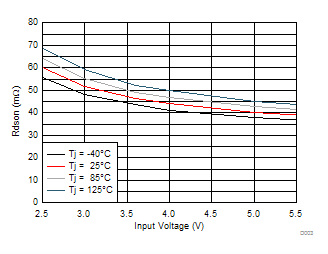 Figure 1. High-Side FET On Resistance
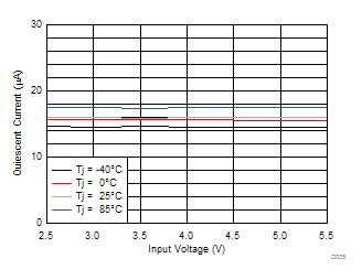 Figure 3. Quiescent Current
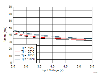 Figure 2. Low-Side FET On Resistance
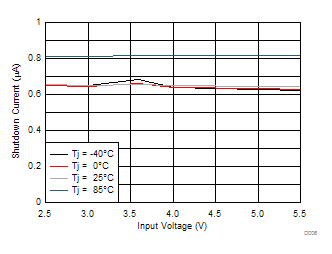 Figure 4. Shutdown Current
7 Detailed Description
7.1 Overview
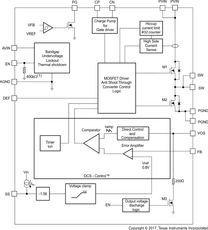
The TLV62095 synchronous step down converter is based on DCS-Control™ (Direct Control with Seamless transition into Power Save Mode). This is an advanced regulation topology that combines the advantages of hysteretic and voltage mode control.
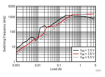
The DCS-Control™ topology operates in PWM (Pulse Width Modulation) mode for medium to heavy load conditions and in Power Save Mode at light load currents. In PWM mode, the converter operates with its nominal switching frequency of 1.4 MHz having a controlled frequency variation over the input voltage range. As the load current decreases, the converter enters Power Save Mode, reducing the switching frequency and minimizing the current consumption of the IC to achieve high efficiency over the entire load current range. DCS-Control™ supports both operation modes using a single building block and therefore has a seamless transition from PWM to Power Save Mode without effects on the output voltage. The TLV62095 offers excellent DC voltage regulation and load transient regulation, combined with low output voltage ripple, minimizing interference with RF circuits.
7.2 Functional Block Diagram
7.3 Feature Description
7.3.1 PWM Operation
At medium to heavy load currents, the device operates with pulse width modulation (PWM) at a nominal switching frequency of 1.4 MHz. As the load current decreases, the converter enters power save mode operation reducing its switching frequency. The device enters power save mode at the boundary to discontinuous conduction mode (DCM).
7.3.2 Power Save Mode Operation
As the load current decreases, the converter enters Power Save Mode operation. During Power Save Mode, the converter operates with reduced switching frequency to maintain high efficiency. Power Save Mode is based on a fixed on-time architecture following Equation 1.
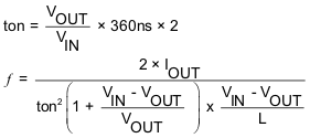
In Power Save Mode, the output voltage rises slightly above the nominal output voltage in PWM mode. This effect is reduced by increasing the output capacitance or the inductor value. This effect is also reduced by programming the output voltage of the TLV62095 lower than the target value.
7.3.3 Low Dropout Operation (100% Duty Cycle)
The device offers low input to output voltage difference by entering 100% duty cycle mode. In this mode the high side MOSFET switch is constantly turned on. This is particularly useful in battery powered applications to achieve longest operation time by taking full advantage of the whole battery voltage range. The minimum input voltage where the output voltage falls below its set point is given by:
Where
RDS(on) = High side FET on-resistance
RL = DC resistance of the inductor
7.4 Device Functional Modes
7.4.1 Enable (EN)
The device is enabled by setting the EN pin to a logic high. Accordingly, shutdown mode is forced if the EN pin is pulled low with a shutdown current of typically 0.6 μA. In shutdown mode, the internal power switches as well as the entire control circuitry are turned off. An internal resistor of 200 Ω discharges the output through the VOS pin smoothly. An internal pull-down resistor of 400 kΩ is connected to the EN pin when the EN pin is low. The pull-down resistor is disconnected when the EN pin is high.
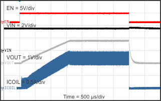
7.4.2 Soft Startup (SS) and Hiccup Current Limit During Startup
To minimize inrush current during startup, the device has an adjustable startup time depending on the capacitor value connected to the SS pin. The device charges the SS capacitor with a constant current of typically 7.5 µA. The feedback voltage follows this voltage divided by 1.56, until the internal reference voltage of 0.8 V is reached. The soft startup operation is completed once the voltage at the SS capacitor has reached typically 1.25 V. The soft startup time is calculated using Equation 3. The larger the SS capacitor, the longer the soft startup time. The relation between the SS pin voltage and the FB pin voltage is estimated using Equation 4.


During startup the switch current limit is reduced to 1/3 of its typical current limit of 5.5A when the output voltage is less than 0.6V. Once the output voltage exceeds typically 0.6V, the switch current limit is released to its nominal value. Thus, the device provides a reduced load current of 1.8A when the output voltage is below 0.6V. Due to this, a small or no startup time may trigger this reduced switch current limit during startup, especially for larger output capacitor applications. This is avoided by using a larger soft start up capacitance which extends the soft startup time. See Short Circuit Protection (Hiccup-Mode) for details of the reduced current limit during startup. Leaving the SS pin floating sets the minimum startup time (around 50 μs).
7.4.3 Voltage Tracking (SS)
The SS pin is externally driven by another voltage source to achieve output voltage tracking. The application circuit is shown in Figure 5. The internal reference voltage follows the voltage at the SS pin with a fraction of 1.56 until the internal reference voltage of 0.8 V is reached. The device achieves ratiometric or coincidental (simultaneous) output tracking, as shown in Figure 6.
The R2 value should be set properly to achieve accurate voltage tracking by taking 7.5 μA soft startup current into account. 1 kΩ or smaller is a sufficient value for R2.
For decreasing the SS pin voltage, the device doesn't sink current from the output when the device is in power save mode. So the resulting decrease of the output voltage may be slower than the SS pin voltage if the load is light. When driving the SS pin with an external voltage, do not exceed the voltage rating of the SS pin which is 7 V.
7.4.4 Short Circuit Protection (Hiccup-Mode)
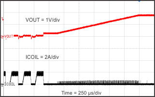
The device is protected against hard short circuits to GND and over-current events. This is implemented by a two level short circuit protection. During start-up and when the output is shorted to GND, the switch current limit is reduced to 1/3 of its typical current limit of 5.5 A. Once the output voltage exceeds typically 0.6 V the current limit is released to its nominal value. The full current limit is implemented as a hiccup current limit. Once the internal current limit is triggered 32 times, the device stops switching and starts a new start-up sequence after a typical delay time of 66 µs passed by. The device repeats these cycles until the high current condition is released.
7.4.5 Output Discharge Function
To make sure the device starts up under defined conditions, the output gets discharged via the VOS pin with a typical discharge resistor of 200 Ω whenever the device shuts down. This happens when the device is disabled or if thermal shutdown, undervoltage lockout or short circuit hiccup-mode is triggered.
7.4.6 Power Good Output
The power good output is low when the output voltage is below its nominal value. The power good becomes high impedance once the output is within 5% of regulation. The PG pin is an open drain output and is specified to sink up to 1mA. This output requires a pull-up resistor to be monitored properly. The pull-up resistor cannot be connected to any voltage higher than the input voltage of the device. The PG output can be left floating if unused. Table 1 shows the PG pin logic.
7.4.7 Undervoltage Lockout
To avoid mis-operation of the device at low input voltages, an undervoltage lockout is included. UVLO shuts down the device at input voltages lower than typically 2.2 V with a 200 mV hysteresis.
7.4.8 Thermal Shutdown
The device goes into thermal shutdown once the junction temperature exceeds typically 150°C with a 20°C hysteresis.
7.4.9 Charge Pump (CP, CN)
The CP and CN pins must attach to an external 10 nF capacitor to complete a charge pump for the gate driver. This capacitor must be rated for the input voltage. It is not recommended to connect any other circuits to the CP or CN pins.
8 Application and Implementation
NOTE
Information in the following applications sections is not part of the TI component specification, and TI does not warrant its accuracy or completeness. TI’s customers are responsible for determining suitability of components for their purposes. Customers should validate and test their design implementation to confirm system functionality.
8.1 Application Information
The TLV62095 is a 4-A high frequency synchronous step-down converter optimized for small solution size, high efficiency and suitable for battery powered applications.
8.2 Typical Applications
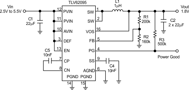
8.2.1 1.8-V Output Converter
 Figure 7. TLV62095 Typical Application Circuit
8.2.1.1 Design Requirements
The design guideline provides a component selection to operate the device within the recommended operating conditions. For the typical application example, the following input parameters are used.
Table 2. Design Parameters
| DESIGN PARAMETER | EXAMPLE VALUE |
|---|---|
| Input voltage range | 2.5 V to 5.5 V |
| Output voltage | 1.8 V |
| Output ripple voltage | < 30 mV |
| Output current rating | 4 A |
Table 3 shows the list of components for the Application Characteristic Curves.
Table 3. List of Components
| REFERENCE | DESCRIPTION | MANUFACTURER |
|---|---|---|
| TLV62095 | High efficiency step-down converter | Texas Instruments |
| L1 | Inductor: 1 µH | Coilcraft XAL4020-102 |
| C1, C2 | Ceramic capacitor: 22 μF | (6.3V, X5R, 0805) |
| C4, C5 | Ceramic capacitor, 10 nF | Standard |
| R1, R2, R3 | Resistor | Standard |
8.2.1.2 Detailed Design Procedure
8.2.1.2.1 Custom Design With WEBENCH® Tools
Click here to create a custom design using the TLV62095 device with the WEBENCH® Power Designer.
- Start by entering the input voltage (VIN), output voltage (VOUT), and output current (IOUT) requirements.
- Optimize the design for key parameters such as efficiency, footprint, and cost using the optimizer dial.
- Compare the generated design with other possible solutions from Texas Instruments.
The WEBENCH Power Designer provides a customized schematic along with a list of materials with real-time pricing and component availability.
In most cases, these actions are available:
- Run electrical simulations to see important waveforms and circuit performance
- Run thermal simulations to understand board thermal performance
- Export customized schematic and layout into popular CAD formats
- Print PDF reports for the design, and share the design with colleagues
Get more information about WEBENCH tools at www.ti.com/WEBENCH.
8.2.1.2.2 Output Filter
The first step is the selection of the output filter components. To simplify this process, Table 4 outlines possible inductor and capacitor value combinations.
Table 4. Output Filter Selection
| INDUCTOR VALUE [µH](3) | OUTPUT CAPACITOR VALUE [µF](2) | ||||
|---|---|---|---|---|---|
| 10 | 22 | 2 x 22 | 100 | 150 | |
| 0.47 | |||||
| 1.0 | √(1) | √ | √ | ||
| 2.2 | |||||
8.2.1.2.3 Inductor Selection
The inductor selection is affected by several parameters like inductor ripple current, output voltage ripple, transition point into Power Save Mode, and efficiency. See Table 5 for typical inductors.
Table 5. Inductor Selection
| INDUCTOR VALUE | COMPONENT SUPPLIER(1) | SIZE (LxWxH mm) | Isat / DCR |
|---|---|---|---|
| 1 µH | Coilcraft XAL4020-102 | 4.0 x 4.0 x 2.1 | 8.75A / 13.2 mΩ |
| 0.47 µH | TOKO DFE322512C | 3.2 x 2.5 x 1.2 | 5.9A / 21 mΩ |
In addition, the inductor has to be rated for the appropriate saturation current and DC resistance (DCR). The inductor needs to be rated for a saturation current as high as the typical switch current limit of 5.5A or according to Equation 5 and Equation 6. Equation 5 and Equation 6 calculate the maximum inductor current under static load conditions. The formula takes the converter efficiency into account. The converter efficiency can be taken from the data sheet graphs or 80% can be used as a conservative approach. The calculation must be done for the maximum input voltage where the peak switch current is highest.


where
ƒ = Converter switching frequency (typically 1.4MHz)
L = Inductor value
η = Estimated converter efficiency (use the number from the efficiency curves or 0.80 as a conservative assumption)
Calculating the maximum inductor current using the actual operating conditions gives the minimum saturation current. A margin of 20% should be added to cover for load transients during operation.
8.2.1.2.4 Input and Output Capacitor Selection
For best output and input voltage filtering, low ESR (X5R or X7R) ceramic capacitors are recommended. The input capacitor minimizes input voltage ripple, suppresses input voltage spikes and provides a stable system rail for the device. A 22-μF or larger input capacitor is recommended. The output capacitor value can range from 10 μF up to 150 μF and beyond. Load transient testing and measuring the bode plot are good ways to verify stability with larger capacitor values.
The recommended typical output capacitor value is 2 x 22 μF (nominal) and can vary over a wide range as outline in the output filter selection table. Ceramic capacitor have a DC-Bias effect, which has a strong influence on the final effective capacitance. Choose the right capacitor carefully in combination with considering its package size and voltage rating.
8.2.1.2.5 Setting the Output Voltage
The output voltage is set by an external resistor divider according to the following equations:


When sizing R2, in order to achieve low quiescent current and acceptable noise sensitivity, use a minimum of 5 µA for the feedback current IFB. Larger currents through R2 improve noise sensitivity and output voltage accuracy.
8.2.1.3 Application Performance Curves
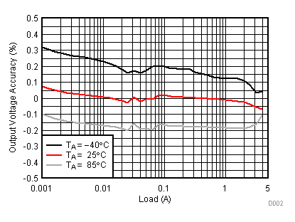
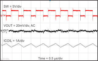
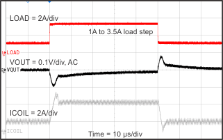
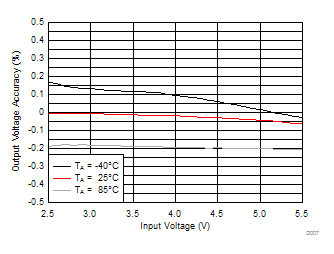
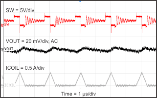
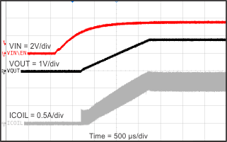
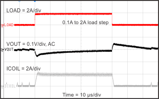
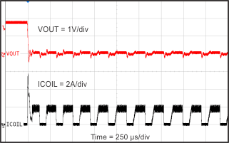
TA = 25°C, VIN = 3.6 V, VOUT = 1.8 V, unless otherwise noted.

