-
TLV916x-Q1 Automotive 16V, 11MHz, Rail-to-Rail Input or Output, Low Offset Voltage, Low Noise Automotive Op Amp SBOSAD7A April 2023 – August 2024 TLV9161-Q1 , TLV9162-Q1 , TLV9164-Q1
PRODUCTION DATA
-
TLV916x-Q1 Automotive 16V, 11MHz, Rail-to-Rail Input or Output, Low Offset Voltage, Low Noise Automotive Op Amp
- 1
- 1 Features
- 2 Applications
- 3 Description
- 4 Pin Configuration and Functions
- 5 Specifications
- 6 Detailed Description
- 7 Application and Implementation
- 8 Device and Documentation Support
- 9 Revision History
- 10Mechanical, Packaging, and Orderable Information
- IMPORTANT NOTICE
Package Options
Mechanical Data (Package|Pins)
Thermal pad, mechanical data (Package|Pins)
Orderable Information
TLV916x-Q1 Automotive 16V, 11MHz, Rail-to-Rail Input or Output, Low Offset Voltage, Low Noise Automotive Op Amp
1 Features
- AEC-Q100 qualified for automotive applications
- Temperature grade 1: –40°C to +125°C, TA
- Device HBM ESD classification level 3A
(≥2500V) - Device CDM ESD classification level C3
(≥1500V)
- Low offset voltage: ±210µV
- Low offset voltage drift: ±0.25µV/°C
- Low noise: 6.8nV/√Hz at 1kHz, 4.2nV/√Hz broadband
- High common-mode rejection: 110dB
- Low bias current: ±10pA
- Rail-to-rail input and output
- Wide bandwidth: 11MHz GBW, unity-gain stable
- High slew rate: 33V/µs
- Low quiescent current: 2.4mA per amplifier
- Wide supply: ±1.35V to ±8V, 2.7V to 16V
- Robust EMIRR performance
2 Applications
3 Description
The TLV916x-Q1 family (TLV9161-Q1, TLV9162-Q1, and TLV9164-Q1) is a family of 16V, general-purpose automotive operational amplifiers. These devices offer exceptional DC precision and AC performance, including rail-to-rail input or output, low offset (±210µV, typical), low-offset drift (±0.25µV/°C, typical), and low noise (6.8nV/√Hz at 1kHz, 4.2nV/√Hz at 10kHz).
Features such as wide differential input voltage range, high short-circuit current (±73mA), and high slew rate (33V/µs) make the TLV916x-Q1 a flexible, robust, and high-performance op amp for automotive applications.
The TLV916x-Q1 family of op amps is available in standard packages and is specified from –40°C to 125°C.
| PART NUMBER(1) | CHANNEL COUNT | PACKAGE | PACKAGE SIZE(2) |
|---|---|---|---|
| TLV9161-Q1 | Single | DBV (SOT-23, 5) | 2.9mm × 2.8mm |
| DCK (SC70, 5) | 2mm × 2.1mm | ||
| TLV9162-Q1 | Dual | D (SOIC, 8) | 4.9mm × 6mm |
| DGK (VSSOP, 8) | 3mm × 4.9mm | ||
| PW (TSSOP, 8) | 3mm × 6.4mm | ||
| TLV9164-Q1 | Quad | D (SOIC, 14) | 8.65mm × 6mm |
| PW (TSSOP, 14) | 5mm × 6.4mm |
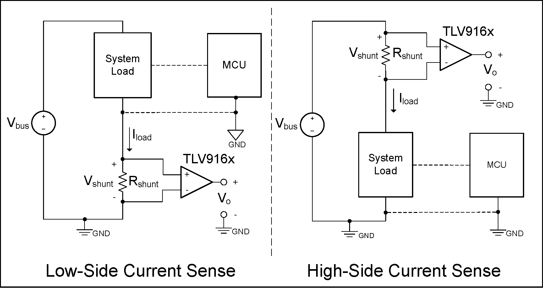
 TLV916x-Q1 in Current-Sensing Applications
4 Pin Configuration and Functions
 Figure 4-1 TLV9161-Q1 DBV
Package,
Figure 4-1 TLV9161-Q1 DBV
Package,5-Pin SOT-23
(Top View)
 Figure 4-2 TLV9161-Q1 DCK
Package,
Figure 4-2 TLV9161-Q1 DCK
Package,5-Pin SC70
(Top View)
| PIN | TYPE(1) | DESCRIPTION | ||
|---|---|---|---|---|
| NAME | SOT-23 (DBV) | SC70 (DCK) | ||
| IN+ | 3 | 1 | I | Noninverting input |
| IN– | 4 | 3 | I | Inverting input |
| OUT | 1 | 4 | O | Output |
| V+ | 5 | 5 | — | Positive (highest) power supply |
| V– | 2 | 2 | — | Negative (lowest) power supply |
 Figure 4-3 TLV9162-Q1 D, PW,
and DGK Package,
Figure 4-3 TLV9162-Q1 D, PW,
and DGK Package,8-Pin SOIC, TSSOP, and VSSOP
(Top View)
| PIN | TYPE(1) | DESCRIPTION | |
|---|---|---|---|
| NAME | NO. | ||
| IN1+ | 3 | I | Noninverting input, channel 1 |
| IN1– | 2 | I | Inverting input, channel 1 |
| IN2+ | 5 | I | Noninverting input, channel 2 |
| IN2– | 6 | I | Inverting input, channel 2 |
| OUT1 | 1 | O | Output, channel 1 |
| OUT2 | 7 | O | Output, channel 2 |
| V+ | 8 | — | Positive (highest) power supply |
| V– | 4 | — | Negative (lowest) power supply |
 Figure 4-4 TLV9164-Q1 D and
PW Package,
Figure 4-4 TLV9164-Q1 D and
PW Package,14-Pin SOIC and TSSOP
(Top View)
| PIN | TYPE(1) | DESCRIPTION | |||
|---|---|---|---|---|---|
| NAME | NO. | ||||
| IN1+ | 3 | I | Noninverting input, channel 1 | ||
| IN1– | 2 | I | Inverting input, channel 1 | ||
| IN2+ | 5 | I | Noninverting input, channel 2 | ||
| IN2– | 6 | I | Inverting input, channel 2 | ||
| IN3+ | 10 | I | Noninverting input, channel 3 | ||
| IN3– | 9 | I | Inverting input, channel 3 | ||
| IN4+ | 12 | I | Noninverting input, channel 4 | ||
| IN4– | 13 | I | Inverting input, channel 4 | ||
| OUT1 | 1 | O | Output, channel 1 | ||
| OUT2 | 7 | O | Output, channel 2 | ||
| OUT3 | 8 | O | Output, channel 3 | ||
| OUT4 | 14 | O | Output, channel 4 | ||
| V+ | 4 | — | Positive (highest) power supply | ||
| V– | 11 | — | Negative (lowest) power supply | ||