SLYS029C July 2021 – December 2024 TMAG5110-Q1 , TMAG5111-Q1
PRODUCTION DATA
- 1
- 1 Features
- 2 Applications
- 3 Description
- 4 Device Comparison Table
- 5 Pin Configuration and Functions
- 6 Specifications
- 7 Detailed Description
- 8 Application and Implementation
- 9 Device and Documentation Support
- 10Revision History
- 11Mechanical, Packaging, and Orderable Information
Package Options
Refer to the PDF data sheet for device specific package drawings
Mechanical Data (Package|Pins)
- DBV|5
Thermal pad, mechanical data (Package|Pins)
Orderable Information
7.3.1.2 2D Magnetic Sensor Response
The TMAG5110-Q1 has two integrated latches that update their results to the OUT1 and OUT2 pins. Each one of these outputs will then have a latch functionality. Figure 7-2 shows the response to different magnetic poles for each output.
The TMAG5111-Q1 outputs are not directly connected to the two integrated latches. Additional processing is available to generate the speed and direction outputs.
 Figure 7-2 Latch Functionality
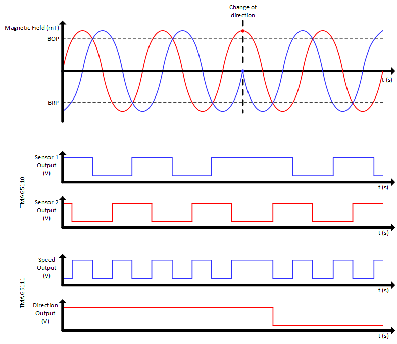
Figure 7-3 shows the magnetic response of both the TMAG5110-Q1 and TMAG5111-Q1 to a sinusoidal field. The sinusoidal curves represents the evaluation of the magnetic seen by both integrated hall sensors.
The TMAG5110-Q1 response shows both outputs reacting to this signal by going low once the field is higher than BOP and going high when the field is lower than BRP.
The TMAG5111-Q1 response shows how those two signals are processed to create a speed output and a direction output.
 Figure 7-3 TMAG511x-Q1 Output
Behavior