SLYS029C July 2021 – December 2024 TMAG5110-Q1 , TMAG5111-Q1
PRODUCTION DATA
- 1
- 1 Features
- 2 Applications
- 3 Description
- 4 Device Comparison Table
- 5 Pin Configuration and Functions
- 6 Specifications
- 7 Detailed Description
- 8 Application and Implementation
- 9 Device and Documentation Support
- 10Revision History
- 11Mechanical, Packaging, and Orderable Information
Package Options
Refer to the PDF data sheet for device specific package drawings
Mechanical Data (Package|Pins)
- DBV|5
Thermal pad, mechanical data (Package|Pins)
Orderable Information
3 Description
The TMAG5110-Q1
and TMAG5111-Q1 are
2-dimensional, dual Hall-effect latches
operating from a 2.5V to 38V power supply. Designed
for high-speed and high-temperature motor applications, these devices are
optimized for applications leveraging rotating magnets. Integrating two
sensors and two separate signal chains the TMAG511x-Q1
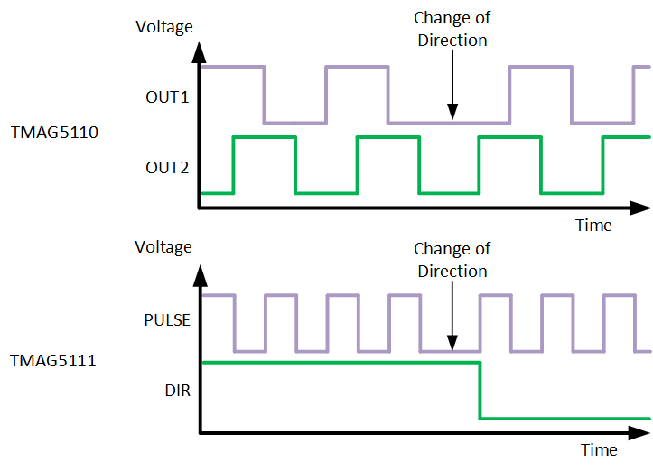
offers two independent digital outputs giving speed and direction
calculation (TMAG5111-Q1) or giving
directly the digital output of each independent latches (TMAG5110-Q1). This high level of
integration allows the use of a single TMAG511x-Q1 device
instead of two separate latches.
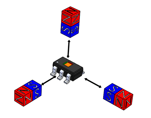
The device is offered in a standard 3mT operating point, as well as a high-sensitivity 1.4mT operating point. The higher magnetic sensitivity provides flexibility in low-cost magnet selection and mechanical component placement. The TMAG511x-Q1 is also available in three 2-axis combination options (X-Y, Z-X, Z-Y) to allow flexible placement of the sensor relative to the magnet.
The device performs consistently across a wide ambient temperature range of –40°C to +125°C.
| PART NUMBER | PACKAGE(1) | PACAKGE SIZE(2) |
|---|---|---|
| TMAG5110-Q1 | DBV (SOT-23, 5) | 2.9mm × 2.8mm |
| TMAG5111-Q1 |
 Device Axis Polarities
 Device Outputs