SLLSF57A August   2022  – April 2024 TMDS1204

PRODUCTION DATA  

  1.   1
  2. Features
  3. Applications
  4. Description
  5. Pin Configuration and Functions
  6. Specifications
    1. 5.1 Absolute Maximum Ratings
    2. 5.2 ESD and Latch-Up Ratings
    3. 5.3 Recommended Operating Conditions
    4. 5.4 Thermal Information
    5. 5.5 Electrical Characteristics
    6. 5.6 Timing Requirements
    7. 5.7 Switching Characteristics
    8. 5.8 Typical Characteristics
  7. Parameter Measurement Information
  8. Detailed Description
    1. 7.1 Functional Block Diagram
    2. 7.2 Feature Description
      1. 7.2.1  4-Level Inputs
      2. 7.2.2  I/O Voltage Level Selection
      3. 7.2.3  HPD_OUT
      4. 7.2.4  Lane Control
      5. 7.2.5  Swap
      6. 7.2.6  Linear and Limited Redriver
      7. 7.2.7  Main Link Inputs
      8. 7.2.8  Receiver Equalizer
      9. 7.2.9  CTLE Bypass
      10. 7.2.10 Adaptive Equalization in HDMI 2.1 FRL
        1. 7.2.10.1 HDMI 2.1 TX Compliance Testing with AEQ Enabled
      11. 7.2.11 HDMI 2.1 Link Training Compatible Rx EQ
      12. 7.2.12 Input Signal Detect
        1. 7.2.12.1 SIGDET_OUT Indicator
      13. 7.2.13 Main Link Outputs
        1. 7.2.13.1 Transmitter Bias
        2. 7.2.13.2 Transmitter Impedance Control
        3. 7.2.13.3 TX Slew Rate Control
        4. 7.2.13.4 TX Pre-Emphasis and De-Emphasis Control
        5. 7.2.13.5 TX Swing Control
        6. 7.2.13.6 Fan-out Buffer
      14. 7.2.14 HDMI DDC Capacitance
      15. 7.2.15 DisplayPort
    3. 7.3 Device Functional Modes
      1. 7.3.1 MODE Control
        1. 7.3.1.1 I2C Mode (MODE = "F")
        2. 7.3.1.2 Pin Strap Modes
          1. 7.3.1.2.1 Pin-Strap: HDMI 1.4 and HDMI 2.0 Functional Description
          2. 7.3.1.2.2 Pin-Strap HDMI 2.1 Function (MODE = "0"): Fixed Rx EQ)
          3. 7.3.1.2.3 Pin-Strap HDMI 2.1 Function (Mode = "1"): Flexible Rx EQ
          4. 7.3.1.2.4 Pin-Strap HDMI 2.1 Function (Mode = "R"): Flexible Rx EQ and Fan-Out Buffer
      2. 7.3.2 DDC Snoop Feature
        1. 7.3.2.1 HDMI Type
        2. 7.3.2.2 HDMI 2.1 FRL Snoop
      3. 7.3.3 Low Power States
    4. 7.4 Programming
      1. 7.4.1 Pseudocode Examples
        1. 7.4.1.1 HDMI 2.1 Source Example with DDC Snoop Disabled and DDC Buffer Disabled
        2. 7.4.1.2 Sink Example
      2. 7.4.2 TMDS1204 I2C Address Options
      3. 7.4.3 I2C Target Behavior
    5. 7.5 Register Maps
      1. 7.5.1 TMDS1204 Registers
  9. Application and Implementation
    1. 8.1 Application Information
    2. 8.2 Typical Source-Side Application
      1. 8.2.1 Design Requirements
      2. 8.2.2 Detailed Design Procedure
        1. 8.2.2.1 Pre-Channel (LAB)
        2. 8.2.2.2 Post-Channel (LCD)
        3. 8.2.2.3 Common Mode Choke
        4. 8.2.2.4 ESD Protection
      3. 8.2.3 Application Curves
    3. 8.3 Typical Sink-Side Application
      1. 8.3.1 Design Requirements
      2. 8.3.2 Detailed Design Procedures
    4. 8.4 Power Supply Recommendations
      1. 8.4.1 Supply Decoupling
    5. 8.5 Layout
      1. 8.5.1 Layout Guidelines
      2. 8.5.2 Layout Example
  10. Device and Documentation Support
    1. 9.1 Documentation Support
      1. 9.1.1 Related Documentation
    2. 9.2 Receiving Notification of Documentation Updates
    3. 9.3 Support Resources
    4. 9.4 Trademarks
    5. 9.5 Electrostatic Discharge Caution
    6. 9.6 Glossary
  11. 10Revision History
  12. 11Mechanical, Packaging, and Orderable Information

Package Options

Mechanical Data (Package|Pins)
Thermal pad, mechanical data (Package|Pins)
Orderable Information

Parameter Measurement Information

GUID-20220701-SS0I-0HDN-W1JM-NKTDWWGST3MR-low.svg Figure 6-1 Power-On Timing Requirements
GUID-20220701-SS0I-KVCH-DQQJ-T15ZQRMBX4SW-low.svg Figure 6-2 TMDS Main Link Test Circuit
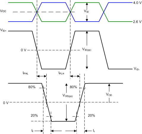
GUID-9C68B477-D07E-44DD-8440-720A8BF82059-low.gif Figure 6-3 Input or Output Timing Measurements
GUID-30399846-D65C-4D58-8E9B-F349A1E43F48-low.gif Figure 6-4 Output Differential Waveform
GUID-268478AA-1D29-4361-91C7-19BE5D168EC8-low.gif Figure 6-5 Output Differential Waveform with De-Emphasis
GUID-08143416-7A09-41D3-A07D-6642AD5DBB6F-low.gif
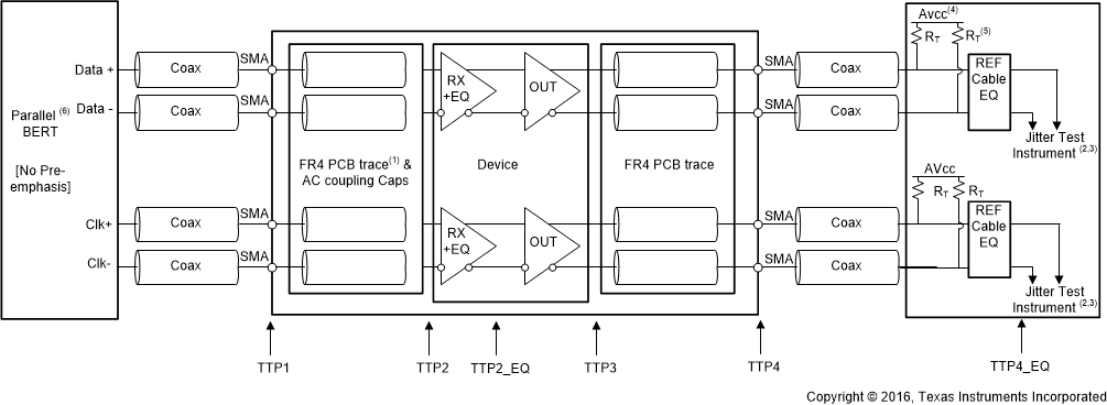
(1) The FR4 trace between TTP1 and TTP2 is designed to emulate 1-12” of FR4, AC-coupling capacitor, connector and another 2” of FR4. Trace width – 4 mils. 100 Ω differential impedance.
(2) All Jitter is measured at a BER of 109. HDMI 2.1 jitter measured at BER 10-10.
(3) Residual jitter reflects the total jitter measured at TTP4 minus the jitter measured at TTP
(4) AVCC = 3.3V.
(5) RT = 50 Ω.
(6) For HDMI 1.4 or 2.0, the input signal from parallel Bert does not have any pre-emphasis or de-emphasis. For HDMI 2.1 FRL, the input signal from BERT will have 2.18dB pre-shoot and −3.1dB de-emphasis. Refer to Recommended Operating Conditions.
Figure 6-6 HDMI Output Jitter Measurement
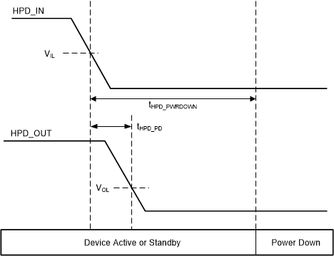
GUID-9C9B4D26-3183-482F-ABA4-063F1B774595-low.gif Figure 6-7 HPD Logic Shutdown and Propagation Timing
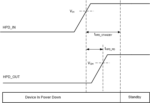
GUID-C21BD680-D73B-452E-9F3F-37A51910CD01-low.gif Figure 6-8 HPD Logic Standby and Propagation Timing
GUID-11E58B14-49EC-4A80-A805-99045CE6D226-low.gif Figure 6-9 I2C SCL and SDA Timing
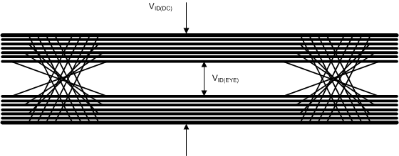
GUID-7C0260F4-A3F5-42EC-81CA-E049AE507B5A-low.gif Figure 6-10 VID(DC) and VID(EYE)