-
TMP107-Q1 Automotive Grade, ±0.4°C Temperature Sensor with Daisy-Chain UART, EEPROM, and Alert Function
- 1 Features
- 2 Applications
- 3 Description
- 4 Revision History
- 5 Description (continued)
- 6 Pin Configuration and Functions
- 7 Specifications
-
8 Detailed Description
- 8.1 Overview
- 8.2 Functional Block Diagram
- 8.3 Feature Description
- 8.4 Device Functional Modes
- 8.5 Programming
- 8.6
Register Map
- 8.6.1 Temperature Register (address = 0h) [reset = 0h]
- 8.6.2 Configuration Register (address = 1h) [reset = A000h]
- 8.6.3 High Limit 1 Register (address = 2h) [reset = 7FFCh]
- 8.6.4 Low Limit 1 Register (address = 3h) [reset = 8000h]
- 8.6.5 High Limit 2 Register (address = 4h) [reset = 7FFCh]
- 8.6.6 Low Limit 2 Register (address = 5h) [reset = 8000h]
- 8.6.7 EEPROM n Register (where n = 1 to 8) (addresses = 6h to Dh) [reset = 0h]
- 8.6.8 Die ID Register (address = Fh) [reset = 1107h]
- 9 Application and Implementation
- 10Power Supply Recommendations
- 11Layout
- 12Device and Documentation Support
- 13Mechanical, Packaging, and Orderable Information
- IMPORTANT NOTICE
Package Options
Mechanical Data (Package|Pins)
- D|8
Thermal pad, mechanical data (Package|Pins)
Orderable Information
TMP107-Q1 Automotive Grade, ±0.4°C Temperature Sensor with Daisy-Chain UART, EEPROM, and Alert Function
1 Features
- AEC-Q100 Qualified with:
- Temperature Grade 1: –40°C to +125°C Ambient Operating Temperature Range
- Device HBM ESD Classification Level 2
- Device CDM ESD Classification Level C6
- High Accuracy (Without Calibration):
- ±0.4°C (max) from –20°C to +70°C
- ±0.55°C (max) from –40°C to +100°C
- ±0.7°C (max) from –55°C to +125°C
- High Resolution: 14 Bits (0.015625°C)
- UART-Compatible, SMAART Wire™ Interface:
- Allows Up To 32 Daisy-Chained Devices
- EEPROM Memory for Unique Addressing, Trip Level Programming, and General-Purpose Storage
- Continuous Conversion and Shutdown Mode for Power Savings
- One-Shot Conversion Mode for Custom Update Rates and Power Savings
- Programmable Alert Feature
- Operating Temperature Range: –55°C to +125°C
- Operating Supply Range: 1.7 V to 5.5 V
- Package: SOIC-8
2 Applications
- Battery Management Systems (BMSs)
- Distributed Temperature Sensing
- Hybrid, Electric, and Power-Train Systems
- Body Control Modules (BCMs)
- Building Automation and HVACs
- Engine Control Units
- Infotainment Processor Management
- Diesel Urea Tanks
3 Description
The TMP107-Q1 digital output temperature sensor supports a total of 32 daisy-chained devices. Each sensor has a unique 5-bit address stored in electrically-erasable programmable memory (EEPROM). The TMP107-Q1 is capable of reading temperatures with a resolution of 0.015625°C, and is accurate to within ±0.4°C in the range from –20°C to +70°C. The TMP107-Q1 is ideal for replacing NTC and PTC thermistors where high accuracy is required.
Device Information(1)
| DEVICE NAME | PACKAGE | BODY SIZE |
|---|---|---|
| TMP107-Q1 | SOIC (8) | 4.90 mm × 3.90 mm |
- For all available packages, see the package option addendum at the end of the datasheet.
5 Description (continued)
The unique 5-bit address stored in the EEPROM is determined during the automated address assignment operation, and is based on the position of each sensor relative to the SMAART wire host. Multiple operating modes provide maximum flexibility in selecting between low power consumption for battery operation, and high update rates for real-time control applications.
The TMP107-Q1 is ideal for extended temperature measurement in a variety of industrial, instrumentation, communication, and environmental applications. The TMP107-Q1 is available in an 8-pin SOIC package and is specified for operation over a temperature range of −55°C to +125°C.
6 Pin Configuration and Functions

Pin Functions
| PIN | I/O | DESCRIPTION | |
|---|---|---|---|
| NO. | NAME | ||
| 1 | V+ | — | Supply voltage, 1.7 V to 5.5 V |
| 2 | R1 | I | Built-in pullup resistor for ALERT1; float or connect to V+ |
| 3 | I/O1 | I/O | SMAART wire input, output 1 |
| 4 | ALERT1 | O | Over- and undertemperature alert. Open-drain output; internally connected to pullup resistor R1. |
| 5 | GND | — | Ground |
| 6 | ALERT2 | O | Over- and undertemperature alert. Open-drain output; internally connected to pullup resistor R2. |
| 7 | I/O2 | I/O | SMAART wire input, output 2 |
| 8 | R2 | I | Built-in pullup resistor for ALERT2; float or connect to V+ |
7 Specifications
7.1 Absolute Maximum Ratings
over operating free-air temperature range (unless otherwise noted)(1)| MIN | MAX | UNIT | ||
|---|---|---|---|---|
| Supply voltage, V+ | 6 | V | ||
| Input voltage | I/O1, I/O2 | –0.3 | (V+) + 0.3 | V |
| R1, R2 | –0.3 | 6 | ||
| ALERT1, ALERT2 | –0.3 | 6 | ||
| Sink current | ALERT1, ALERT2 | 10 | mA | |
| Temperature | Operating junction | –55 | 150 | °C |
| Storage, Tstg | –60 | 150 | ||
7.2 ESD Ratings
| VALUE | UNIT | |||
|---|---|---|---|---|
| V(ESD) | Electrostatic discharge | Human-body model (HBM), per AEC Q100-002(1) | ±2000 | V |
| Charged-device model (CDM), per AEC Q100-011 | ±1000 | |||
7.3 Recommended Operating Conditions
over operating free-air temperature range (unless otherwise noted)| MIN | NOM | MAX | UNIT | ||
|---|---|---|---|---|---|
| Supply voltage, V+ | 1.7 | 3.3 | 5.5 | V | |
| Operating free-air temperature, TA | –55 | 125 | °C | ||
7.4 Thermal Information
| THERMAL METRIC(1) | TMP107-Q1 | UNIT | |
|---|---|---|---|
| D (SOIC) | |||
| 8 PINS | |||
| RθJA | Junction-to-ambient thermal resistance | 116.3 | °C/W |
| RθJC(top) | Junction-to-case (top) thermal resistance | 62.5 | °C/W |
| RθJB | Junction-to-board thermal resistance | 56.6 | °C/W |
| ψJT | Junction-to-top characterization parameter | 14.6 | °C/W |
| ψJB | Junction-to-board characterization parameter | 56.0 | °C/W |
| RθJC(bot) | Junction-to-case (bottom) thermal resistance | N/A | °C/W |
7.5 Electrical Characteristics
At TA = –55°C to 125°C and V+ = +1.7 V to +5.5 V (unless otherwise noted). Typical values at TA = 25°C and V+ = 3.3 V.| PARAMETER | TEST CONDITIONS | MIN | TYP | MAX | UNIT | |
|---|---|---|---|---|---|---|
| TEMPERATURE INPUT | ||||||
| Temperature range | –55 | 125 | °C | |||
| Temperature resolution | 0.015625 | °C | ||||
| Temperature accuracy (error) | –20°C to +70°C; one-shot mode, bus inactive | ±0.125 | ±0.4 | °C | ||
| –40°C to +100°C; one-shot mode, bus inactive | ±0.125 | ±0.55 | ||||
| –55°C to +125°C; one-shot mode, bus inactive | ±0.5 | ±0.7 | ||||
| ADC resolution | 14 | Bits | ||||
| DIGITAL OUTPUT (ALERT1, ALERT2) | ||||||
| VOL | Low-level output voltage | IOUT = –1 mA | 0 | 0.02 | 0.4 | V |
| IOH | High-level output leakage current | VO = V+ | 0.1 | 1 | μA | |
| RPU | Pullup resistors | 75 | 100 | 125 | kΩ | |
| DIGITAL INPUT/OUTPUT (I/O1, I/O2) | ||||||
| VIH | High-level input voltage | 0.7 (V+) | (V+) + 0.3 | V | ||
| VIL | Low-level input voltage | –0.3 | 0.3 (V+) | V | ||
| IIN | Input current | 0 V < VIN < (V+) + 0.3 V | –1 | 1 | μA | |
| VOL | Low-level output voltage | IOUT = –1 mA | 0 | 0.1 | 0.4 | V |
| VOH | High-level output voltage | IOUT = 1 mA | (V+) – 0.4 | (V+) – 0.1 | V+ | V |
| Short-circuit current | Short-circuit I/O1 and I/O2 to ground or V+, V+ = 5 V |
60 | mA | |||
| DEVICE TIMING | ||||||
| Conversion time | One-shot mode | 12 | 15 | 18 | ms | |
| Conversion rate | Programmable | 1/16 | 62 | Conv/s | ||
| Device timeout time | Any communication | 35 | 40 | ms | ||
| Global address-initialize command | 1 | 1.25 | s | |||
| EEPROM | ||||||
| Programming time | V+ > 1.8 V | 7 | ms | |||
| Number of writes | V+ > 1.8 V | 1000 | 100,000 | Times | ||
| Data retention time | 10 | Years | ||||
| POWER SUPPLY | ||||||
| V+ | Operating supply range | 1.7 | 3.3 | 5.5 | V | |
| EEPROM write | 1.8 | 3.3 | 5.5 | V | ||
| IQ | Quiescent current | ADC conversion on, SMAART wire bus inactive |
200 | 400 | μA | |
| ADC conversion on, SMAART wire bus active (bus baud rate = 57.6 kBd) | 300 | |||||
| ADC conversion off, SMAART wire bus active (bus baud rate = 57.6 kBd) | 100 | |||||
| 1 conversion per second average, SMAART wire bus inactive |
16 | 35 | ||||
| EEPROM write (ADC conversion off) | 400 | |||||
| ISD | Shutdown current | SMAART wire bus inactive (I/O1, I/O2 = V+) | 3.8 | 10 | μA | |
| Power-on reset voltage | Supply voltage rising | 1.4 | V | |||
7.6 Timing Requirements
| MIN | NOM | MAX | UNIT | ||
|---|---|---|---|---|---|
| FROM HOST TO THE TMP107-Q1 | |||||
| 1/tBAUD | SMAART bus baud rate | 4.8 | 115.4 | kBd | |
| tRISE + tJITTER | SMAART bus transition from low to high + edge timing variance | 15 | % of (1/baud) | ||
| tFALL + tJITTER | SMAART bus transition from high to low + edge timing variance | 15 | % of (1/baud) | ||
| FROM THE TMP107-Q1 TO HOST OR NEXT TMP107-Q1 IN DAISY-CHAIN | |||||
| tJITTER | Edge timing variance | 1 | µs | ||
| tSKEW | Average phase shift between IO1 and IO2 | 33 | ns | ||
| tRISE | SMAART bus transition from low to high, 10-pF load | 10 | ns | ||
| tFALL | SMAART bus transition from high to low, 10-pF load | 10 | ns | ||
 Figure 1. Timing Diagram
7.7 Typical Characteristics
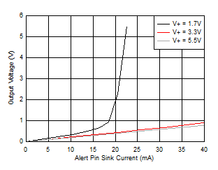
at TA = 25°C and V+ = 3.3 V (unless otherwise noted)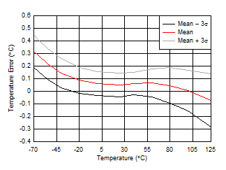
| One-shot mode, specified from –55ºC to +125ºC only |
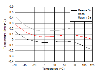
| One-shot mode, V+ = 1.7 V, specified from –55ºC to +125ºC only | ||
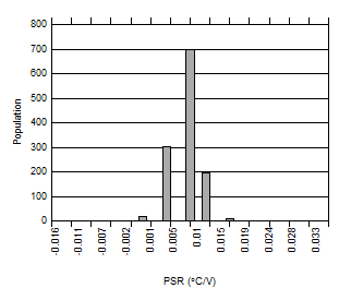
| One-shot mode, V+ = 1.7 V to 5.5 V |
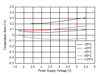
| One-shot mode |
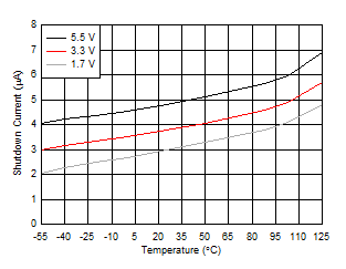
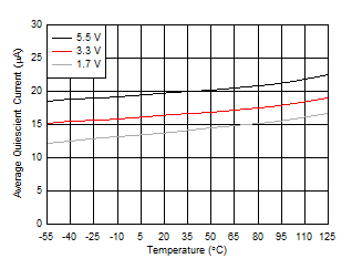
| 1 conversion per second |
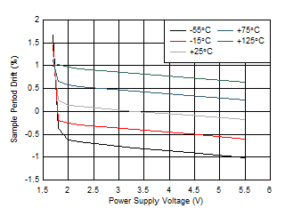
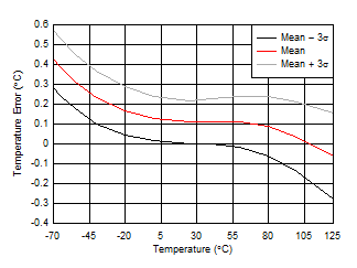
| One-shot mode, V+ = 5.5 V, specified from –55ºC to +125ºC only |
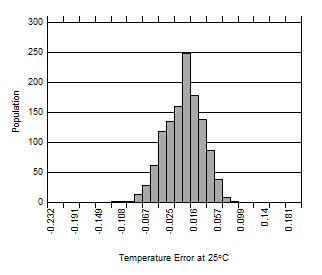
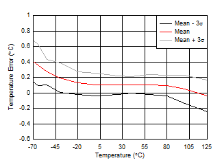
| Continuous-conversion mode, maximum conversion rate, |
| bus inactive |
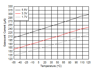
| No bus communication |
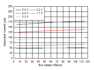
| Shutdown mode |
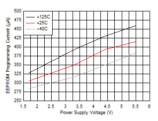
vs Power Supply Voltage
