SNIS227C May 2021 – June 2022 TMP126-Q1
PRODUCTION DATA
- 1 Features
- 2 Applications
- 3 Description
- 4 Revision History
- 5 Device Comparison
- 6 Pin Configuration and Functions
- 7 Specifications
-
8 Detailed Description
- 8.1 Overview
- 8.2 Functional Block Diagram
- 8.3 Feature Descriptions
- 8.4 Device Functional Modes
- 8.5 Programming
- 8.6 Register Map
- 9 Application and Implementation
- 10Power Supply Recommendations
- 11Layout
- 12Device and Documentation Support
- 13Mechanical, Packaging, and Orderable Information
Package Options
Mechanical Data (Package|Pins)
Thermal pad, mechanical data (Package|Pins)
Orderable Information
8.5.2.5.1 Cyclic Redundancy Check Implementation
Table 8-2 defines the CRC calculation rule.
| Temperature | Digital Output |
|---|---|
| CRC Width | 16 bits |
| Polynomial | X16 + X12 + X5 + 1 (1021h) |
| Initial seed value | FFFFh |
| Input data reflected | No |
| Result data reflected | No |
| XOR value | 0000h |
| Example | CRC of 0xABCD = 0xD46A |
Figure 8-17 shows the CRC Module block diagram. The CRC calculation is done on the command word and the data block. The module consists of a 16-bit shift register and 3 exclusive-OR gates. The register starts with the seed value FFFFh and the module performs an XOR function and shifts its content until the last bit of the register string is used. The final value of the shift register checksum is output onto the SIO line by the TMP126-Q1 at the end of the data block for the host to validate the transaction.
 Figure 8-17 CRC Module
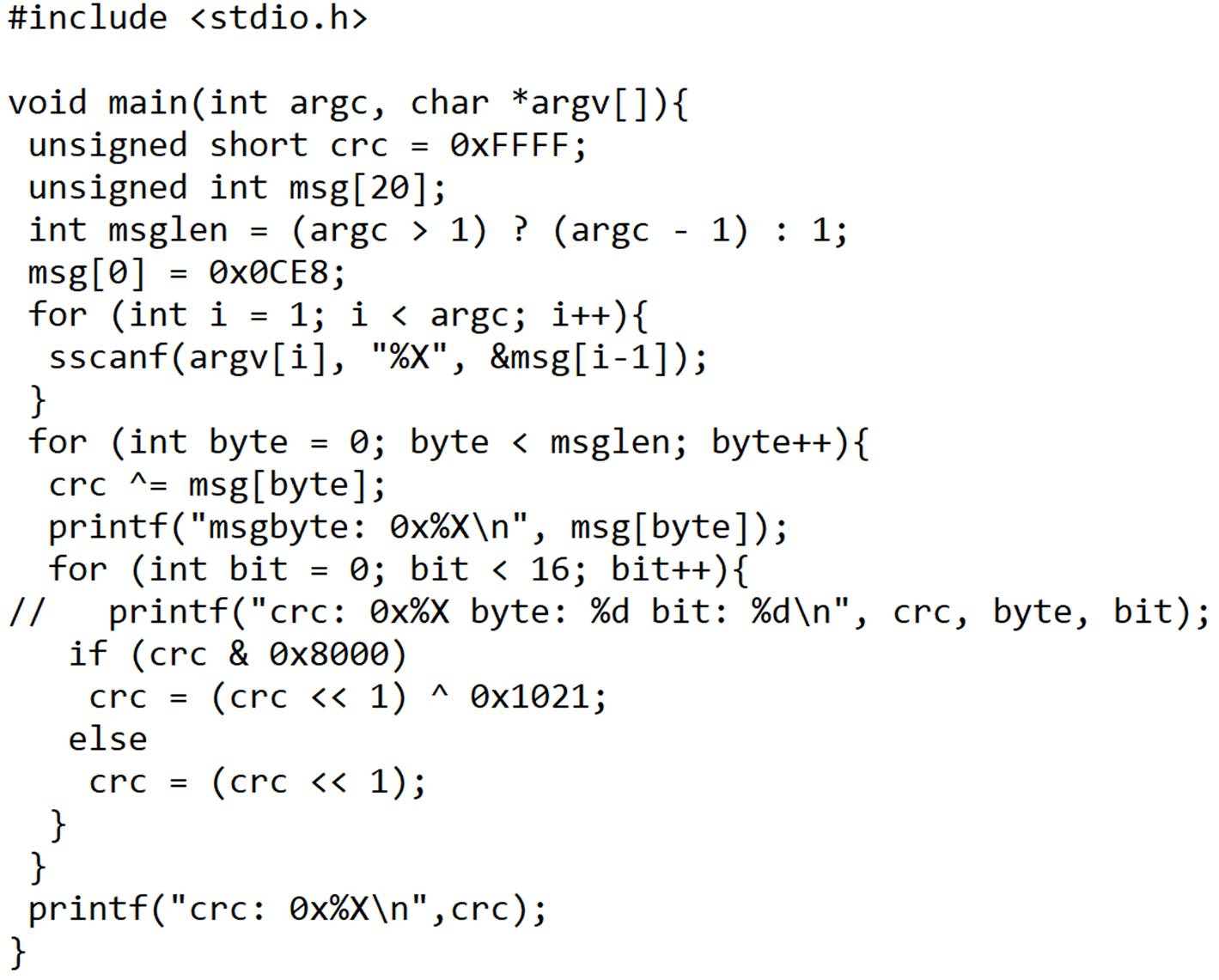
The following is an example of C code programming example to calculative the communication CRC:
 Figure 8-18 CRC Calculation C Code
Example.