SNIS218B September 2019 – June 2022 TMP390-Q1
PRODUCTION DATA
- 1 Features
- 2 Applications
- 3 Description
- 4 Revision History
- 5 Pin Configuration and Functions
- 6 Specifications
- 7 Detailed Description
- 8 Application and Implementation
- 9 Power Supply Recommendations
- 10Layout
- 11Device and Documentation Support
- 12Mechanical, Packaging, and Orderable Information
Package Options
Mechanical Data (Package|Pins)
- DRL|6
Thermal pad, mechanical data (Package|Pins)
Orderable Information
8.2.3 One Channel Operation for Hot Trip Point up to 124°C
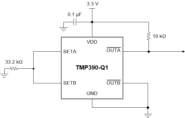
Figure 8-5 shows the TMP390-Q1 configured for one channel operation, with a single resistor to set the hot trip point and hysteresis. Table 8-2 shows the possible resistor values and hysteresis values that may be used for one channel applications.
 Figure 8-5 TMP390-Q1 One Channel (Hot) Operation Example Circuit With 78°C Trip Point and 5°C Hysteresis
Table 8-2 Single Resistor One Channel Setting
| NOMINAL 1% RESISTOR (KΩ) | CHANNEL A TRIP TEMPERATURE (°C) | HYSTERESIS (°C) |
|---|---|---|
| 10.5 | 62 | 5 |
| 12.1 | 64 | 5 |
| 14.0 | 66 | 5 |
| 16.2 | 68 | 5 |
| 18.7 | 70 | 5 |
| 21.5 | 72 | 5 |
| 24.9 | 74 | 5 |
| 28.7 | 76 | 5 |
| 33.2 | 78 | 5 |
| 38.3 | 80 | 5 |
| 44.2 | 82 | 5 |
| 51.1 | 84 | 5 |
| 59.0 | 86 | 5 |
| 68.1 | 88 | 5 |
| 78.7 | 90 | 5 |
| 90.0 | 92 | 5 |
| 105 | 94 | 10 |
| 121 | 96 | 10 |
| 140 | 98 | 10 |
| 162 | 100 | 10 |
| 187 | 102 | 10 |
| 215 | 104 | 10 |
| 249 | 106 | 10 |
| 287 | 108 | 10 |
| 332 | 110 | 10 |
| 383 | 112 | 10 |
| 442 | 114 | 10 |
| 511 | 116 | 10 |
| 590 | 118 | 10 |
| 681 | 120 | 10 |
| 787 | 122 | 10 |
| 909 | 124 | 10 |