SNIS216 November 2019 TMP392
PRODUCTION DATA.
- 1 Features
- 2 Applications
- 3 Description
- 4 Revision History
- 5 Pin Configuration and Functions
- 6 Specifications
- 7 Detailed Description
- 8 Application and Implementation
- 9 Power Supply Recommendations
- 10Layout
- 11Device and Documentation Support
- 12Mechanical, Packaging, and Orderable Information
Package Options
Mechanical Data (Package|Pins)
- DRL|6
Thermal pad, mechanical data (Package|Pins)
Orderable Information
8.2.1 Simplified Application Schematic
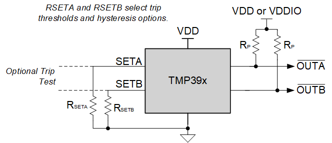
Figure 9 shows the simplified schematic where RSETA and RSETB are used to set channel A trip point (SETA) and channel B trip point and hysteresis for both channels (SETB). SETA and SETB can be programmed at a variety of temperatures based on the device, as described in Table 1 for channel A trip point, and Table 2 for channel B trip point and hysteresis for both channels. OUTA and OUTB outputs correspond to the temperature threshold detection at SETA and SETB, respectively.
 Figure 9. Simplified Schematic