SBOS371B August 2006 – October 2014 TMP401
PRODUCTION DATA.
- 1 Features
- 2 Applications
- 3 Description
- 4 Revision History
- 5 Pin Configuration and Functions
- 6 Specifications
- 7 Detailed Description
- 8 Application and Implementation
- 9 Power-Supply Recommendations
- 10Layout
- 11Device and Documentation Support
- 12Mechanical, Packaging, and Orderable Information
Package Options
Mechanical Data (Package|Pins)
- DGK|8
Thermal pad, mechanical data (Package|Pins)
Orderable Information
8 Application and Implementation
NOTE
Information in the following applications sections is not part of the TI component specification, and TI does not warrant its accuracy or completeness. TI’s customers are responsible for determining suitability of components for their purposes. Customers should validate and test their design implementation to confirm system functionality.
8.1 Application Information
The TMP401 is a remote temperature sensor monitor that includes a built-in local temperature sensor. The remote temperature sensor diode-connected transistors are typically low-cost, NPN- or PNP-type transistors or diodes that are an integral part of microcontrollers, microprocessors, or FPGAs.
Remote accuracy is ±1°C for multiple device manufacturers, with no calibration required. The two-wire serial interface accepts SMBus write, read, send, and receive byte commands to program alarm thresholds and to read temperature data.
Features included in the TMP401 are series resistance cancellation, wide remote temperature measurement range (–40°C to +150°C), diode fault detection, and temperature alert functions.
8.2 Typical Application

8.2.1 Design Requirements
The TMP401 device requires pull-up resistors on the SCL, SDA, ALERT/THERM2, and THERM pins. The recommended value for the pull-up resistors is 10-kΩ. A 0.1-μF bypass capacitor on the supply is recommended, as shown in Figure 24. The SCL and SDA lines can be pulled up to a supply that is equal to or higher than V+ through the pull-up resistors, but not to exceed (V+) + 0.5 V.
8.2.2 Detailed Design Procedure
Place the TMP401 device in close proximity to the heat source to be monitored, with proper layout for good thermal coupling. This placement ensures that temperature changes are captured within the shortest possible time interval. To maintain accuracy in applications that require air or surface temperature measurement, care must be taken to isolate the package and leads from ambient air temperature. A thermally-conductive adhesive is helpful in achieving accurate surface temperature measurement.
8.2.2.1 Filtering
Remote junction temperature sensors are usually implemented in a noisy environment. Noise is most often created by fast digital signals, and can corrupt measurements. The TMP401 has a built-in, 65-kHz filter on the inputs of D+ and D– to minimize the effects of noise. However, a bypass capacitor placed differentially across the inputs of the remote temperature sensor is recommended to make the application more robust against unwanted coupled signals. The value of the capacitor must be between 100 pF and 1 nF. Some applications attain better overall accuracy with additional series resistance. When series resistance is added, the value must not be greater than RS = 3 kΩ. If filtering is needed, the suggested component values are 100 pF and 50 Ω on each input. Exact values are application-specific.
8.2.3 Application Curves
8.2.3.1 Series Resistance Cancellation
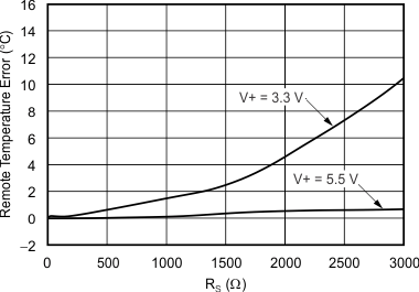
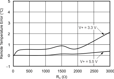
Series resistance in an application circuit that typically results from printed circuit board (PCB) trace resistance and remote line length (see Figure 11) is automatically cancelled by the TMP401, preventing what otherwise results in a temperature offset. When using a 5-V supply voltage, a total of up to RS = 3 kΩ of series line resistance is cancelled by the TMP401, eliminating the need for additional characterization and temperature offset correction. Limit series line resistance to 500 Ω total when using a 3.3-V supply voltage. See Figure 25 and Figure 26 for details on the effect of series resistance and power-supply voltage on sensed remote temperature error.
8.2.3.2 Differential Input Capacitance
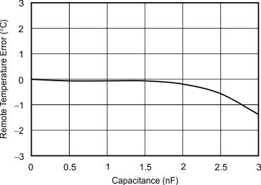
The TMP401 tolerates differential input capacitance of up to 1000 pF with minimal change in temperature error. The effect of capacitance on sensed remote temperature error is illustrated in Figure 27.


